 |
|||
|
|
|||
|
|
|||
| ||||||||||
|
|
 (2) Refer to figures 163 and 164 and re-
(2) Remove turbosupercharger assembly
verse the sequence of illustrations and
following the sequence of illustrations
instructions to install the crankshaft
and instructions for figures 44 through
rear oil seal and housing assembly on
47 and 49 through 52.
the engine.
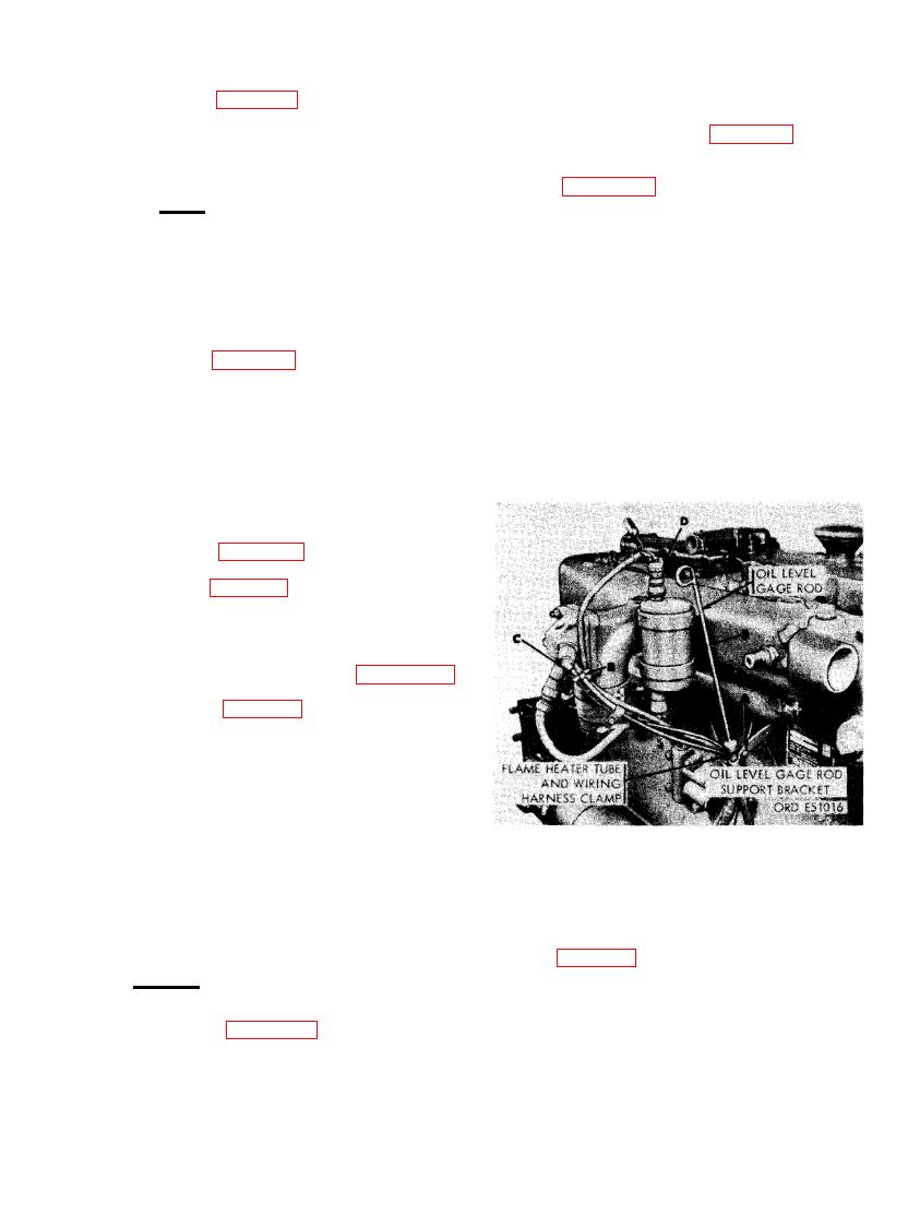
(3) Figure 168. (A) Remove No. 12 plain
Note. Apply a light coating of lubricant
nut, No. 12 lock washer, and No. 12
around lip of oil seal before installing
x 5/8 machine screw securing oil level
seal and housing assembly on engine.
gage rod support to oil gage rod bracket.
Lubricant will prevent lip of seal from
(B) Disconnect 1/4- inch tube nut on
crimping as seal is slipped over pilot
flame heater fuel return-to- solenoid
sleeve or seal surface of crankshaft
valve tube from 1/8- inch pipe union in
flange. Use a seal pilot sleeve to pre-
flame heater nozzle and holder assem-
vent damage to seal lip.
bly. (C) Disconnect 1/8- inch tube nut
on flame heater fuel solenoid valve-to-
(3) Refer to figures 159 and 160 and reverse
flame heater nozzle tube from 1/4 tube
the sequence of illustrations and in-
x 1/8 pipe, 90 degree elbow in flame
structions to install the flywheel. Re-
heater nozzle and holder assembly.
move pilot after flywheel is properly
(D) Disconnect flame heater ignition
positioned with all cap screw holes in
lead from flame heater ignition unit.
flywheel alined with screw holes in
(E) Remove oil level gage rod from rod
crankshaft. Tighten the six 1/2 x 1- 1/8
support.
place bolts to a torque of 650 to 700
pound inches.
(4) Check flywheel runout following instruc-
tions for figure 161.
(5) Refer to figure 158 and reverse the se-
quence of instructions to install trans-
mission adapter.
(6) Check transmission adapter face runout
following instructions for figure 162.
(7) Refer to figures 88 and 89 and reverse
the sequence of illustrations and in-
structions to install clutch driven mem-
ber and clutch cover assemblies.
a. General. When it becomes necessary to
remove the exhaust manifold assembly for re-
placement or for gasket replacement, the intake
NECTING INTAKE MANIFOLD FLAME
manifold will also have to be removed. Both the
HEATER FUEL TUBES, IGNITION
LEAD, AND OIL LEVEL GAGE
at the same time, neither can be removed
SUPPORT BRACKET.
separately.
(4) Figure 169. (A) Disconnect turbosuper-
charger oil inlet tube from 3/8 tube x
b. Removal. Remove exhaust manifold as
3/8 pipe, 90 degree elbow in crankcase
folhws.
and remove tube. (B) Remove six 7/16-
inch self- locking nuts and 7/16- inch
(1) Refer to figures 109 through 112 and
flat washers securing bottom flanges
follow the sequence of illustrations and
of exhaust manifold sections to cylinder
instructions to remove the thermostat
heads. (C) Remove oil level gage rod
housing.
117
|
|
Privacy Statement - Press Release - Copyright Information. - Contact Us |