 |
|||
|
|
|||
|
Page Title:
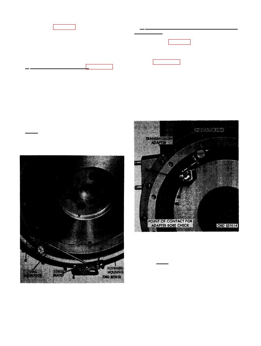
FIGURE 161. CHECKING FLYWHEEL RUN USING A DIAL INDICATOR. |
|
||
| ||||||||||
|
|
 (2) Refer to figure 159 and reverse the se-
d. Install and Check Transmission Adapter
quence of instructions to install the fly-
Face Runout.
wheel. Remove pilot after flywheel is
properly positioned and all cap screw
(1) Refer to figure 158 and reverse the se-
holes aline. Tighten the six 1/2 x 1- 1/8
quence of instructions to install trans-
cap screws to a torque of 650 to 700
mission adapter.
pound inches.
(2) Figure 162. (A) Mount a magnetic base
c. Check Flywheel Runout. Figure 161. (A)
dial indicator on face of flywheel. Set
Install a small steel plate on flywheel housing
dial indicator arm against transmission
and secure to transmission adapter stud using
adapter face. (B) Turn the crankshaft
a 3/8-inch plain nut. (B) Mount magnetic base
one complete revolution and check
dial indicator on steel plate. Position indicator
adapter face runout. Exert pressure
arm against flywheel face. Dial indicator gage
against flywheel to eliminate the pos-
must contact a clean surface on the flywheel
sibility of crankshaft end play causing a
during runout check. (C) Rotate flywheel one
false reading. Maximum runout should
full revolution while pressing against crankshaft
not exceed 0 .008- inch.
to eliminate the possibility of a false reading
due to end play. Repeat the checking procedure
to insure an accurate reading.
Note. Replace flywheel if runout exceeds a
maximum of 0.008-inch.
ADAPTER FACE AND BORE RUNOUT
USING A DIAL INDICATOR.
Note. When transmission adapter face
runout exceeds 0.008-inch, check to
determine the cause of excessive run-
out. Runout can be caused by foreign
material wedged between the transmis-
sion adapter and face of flywheel hous-
ing. If no foreign material is present,
replace the adapter. (C) Check trans-
mission adapter bore in the same man-
ner except ball point on dial indicator
USING A DIAL INDICATOR.
114
|
|
Privacy Statement - Press Release - Copyright Information. - Contact Us |