 |
|||
|
|
|||
|
|
|||
| ||||||||||
|
|
 (3) R e p l a c e crankshaft when journals are
(6) Inspect crankshaft gear key (M, fig. 351)
grooved,
burned,
deeply
nicked,
for nicks and snug fit in keyway. Nicks
scratched, galled, scuffed, or if crank-
in key may be removed with a fine oil
s h a f t is discolored from overheating.
stone. A loose key must be replaced.
Repair minor imperfections in journals
(7) I n s p e c t
crankpin plug (MM-3) (early
by polishing with crocus cloth dipped
i n dry-cleaning s o l v e n t o r m i n e r a l
models)
for bent condition or cracks
spirits paint thinner.
around
bolt hole. Replace bent or
cracked
plugs.
(4) R e p l a c e a c r a c k e d c r a n k s h a f t o r a
167. REPAIR
c r a n k s h a f t showing evidence of wear
due to bent or twisted connecting rods.
a . Regrinding. C r a n k s h a f t s having out-of-
round bearing journals or when either connect-
b . Crankshaft Bushing-type Pilot Bearing
i n g rods or main bearing journals are worn
Replacement (fig. 337).
b e y o n d limits specified in repair and rebuild
(1) Remove damaged or worn bushing-type
s t a n d a r d s (par. 292), regrind crankshaft to a
limit of 0.010 or 0.020-inch undersize. Under-
s i z e bearing s e t s are available for rebuild.
following step A for figure 94.
The crankshaft must be held to limits established
in repair and rebuild standards and to the
(2) Install new bushing-type pilot bearing
following instructions.
( M M - 6 , fig. 322) (par. 67). Refer to
(1) S u r f a c e roughness on crankpins and
j o u r n a l s must not exceed 20 micro
168. ASSEMBLY
inches.
(2) C r a n k s h a f t must be inspected by the
Refer to figures 334 and 335 and reverse the
electro magnaflux method for fractures
sequence of instructions to assembly the crank-
and surface cracks after finishing.
shaft.
Section IV. REBUILD OF CAMSHAFT ASSEMBLY AND THRUST PLATE
169. DISASSEMBLY
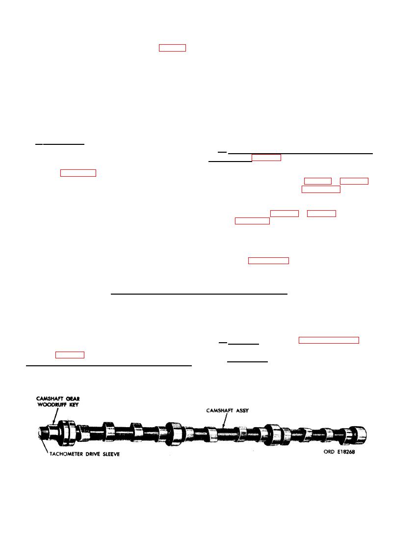
The only component part removed from the
a . Cleaning. Refer to paragraph 152 for
camshaft assembly is the camshaft gear Wood-
general cleaning procedures.
ruff key (fig. 338). The tachometer drive sleeve
--. I n s p e c t i o n .
b
is a press fit in the end of the camshaft and
is not removed unless it is damaged.
(1) Camshaft. Inspect camshaft (AM, fig.
208
|
|
Privacy Statement - Press Release - Copyright Information. - Contact Us |