 |
|||
|
|
|||
|
|
|||
| ||||||||||
|
|
 166. CLEANING AND INSPECTION
(2) Inspect radii of crankshaft connecting
rod journals (fig. 334) for evidence of
Note. The key letters shown below in paren-
specific points of wear or damage that
theses refer to figure 322 except where other-
would indicate a bent or twisted con-
wise indicated.
necting rod has been rubbing or touching
crankshaft during operation.
a. Cleaning. Refer to paragraph 152d for
general cleaning instructions for the crankshaft
(3) Check diameters of main bearing jour-
(MM-5). Thoroughly clean the crankshaft oil
nals (fig. 334) and connecting rod jour-
passages with compressed air and brass wire
nals against limits specified in repair
probes as required. Refer to figure 336 for
and rebuiid standards (par. 292). Check
location of connecting rod journal crankpin oil
runout of crankshaft by supporting end
passages in early model engines.
journals in "V" blocks and measuring
the runout at the center journals with
a dial indicator. Runout should not ex-
ceed 0.003-inch at No. 4 main bearing
journal. Out-of-round must not exceed
0.0005-inch.
(4) I n s p e c t journals for nicks, burs,
grooves, scratches, galling, scuffing,
or discoloration. Mark minor defect
areas for repair.
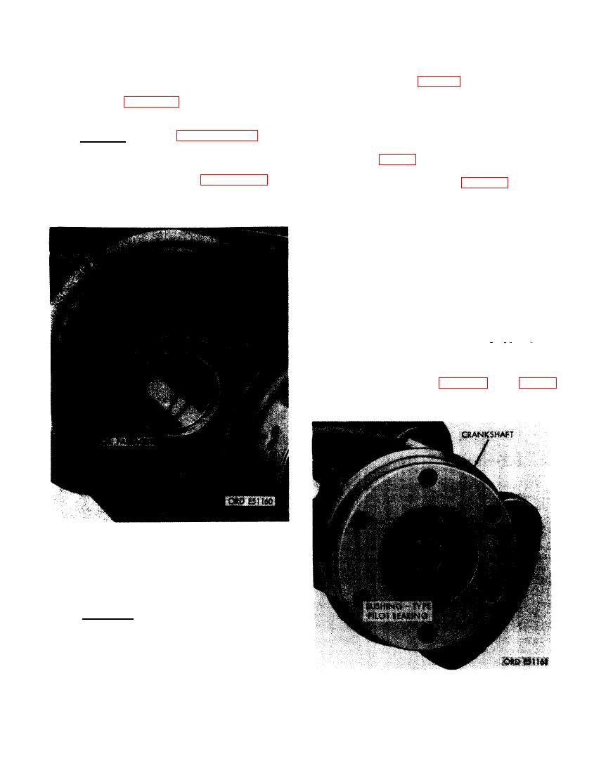
(5) Check crankshaft bushing-type pilot
bearing (MM-6) for cracks or other
visible damage. Check bore of bearing
against limits specified in repair and
ure 337.
CRANKSHAFT CRANKPIN OIL HOLES
(EARLY MODEL ENGINES).
--. Inspection.
b
(1) Inspect crankshaft (MM-5) for cracks
with magnaflux equipment when avail-
able. When magnaflux equipment is not
available use a magnifying glass and a
strong light. Pay particular attention to
FIGURE 337. LOCATION OF BUSHING-TYPE
areas around crankshaft oil holes and
BEARING IN CRANKSHAFT ASSEMBLY.
fillets adjacent to the crank cheeks.
207
|
|
Privacy Statement - Press Release - Copyright Information. - Contact Us |