 |
|||
|
|
|||
|
Page Title:
Section III. REBUILD OF CRANKSHAFT ASSEMBLY |
|
||
| ||||||||||
|
|
 Section III. REBUILD OF CRANKSHAFT ASSEMBLY
visible inside the crankpin holes as shown in
164. GENERAL
a . This section covers disassembly, clean-
165. DISASSEMBLY
ing, inspection, repair, and assembly of the
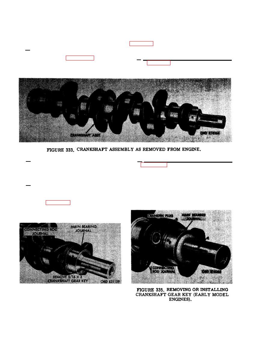
crankshaft assembly. Figure 333 illustrates a
a. Late Model Engine Crankshaft Assembly.
crankshaft assembly as removed from the en-
Refer to figure 334 and disassemble the crank-
gine.
shaft assembly.
b. Late model engines, serial Nos. 5261 and
b . Early Model Engine Crankshaft Assem-
up, have a crankshaft in which the drilled oil
bly. Figure 335. (A) Remove six 1/16 x 3/4
passages do not enter the crankpin journal bore,
cotter pins, 1/4-inch slotted nuts, and 1/4 x
eliminating the need for crankpin plugs.
3-3/8 cap screws. (B) Remove 12 crankpin
plugs. (C) Remove 5/16 x 3 crankshaft gear
c . Early model engines, serial Nos. 1001
key.
through 5260 are equipped with a crankshaft
which utilizes connecting rod journal crankpin
plugs. The journals have drilled oil passages
as shown in figure 336. Crankpin plugs seal the
connecting rod journal bores at the ends, main-
taining a pressurized lubrication system. Early
model crankshafts are identified by oil passages
CRANKSHAFT GEAR KEY (LATE MODEL
ENGINES).
206
|
|
Privacy Statement - Press Release - Copyright Information. - Contact Us |