 |
|||
|
|
|||
|
Page Title:
Section V. REBUILD OF PISTONS, RINGS, PISTON PINS, AND CONNECTING RODS |
|
||
| ||||||||||
|
|
 322) for cracks using magnaflux equip-
evidence of wear. Refer to figure 514,
ment. When magnaflux equipment is not
repair and rebuild. If plate is grooved
available use a magnifying glass and a
or worn excessively, replace.
strong light. Inspect camshaft lobes and
bearing surfaces for wear, scuffing,
and scoring. Check camshaft against
limits specified in repair and rebuild
standards (par. 292). Inspect camshaft
a . Repair. No repairs can be made to the
for stripped or damaged threads. Check
camshaft (AM-2, fig. 322) except for the removal
keyway for damage.
of minor scratches and nicks from camshaft
lobes and bearing contact surfaces. Remove
(2) Woodruff key. Inspect camshaft gear
minor scratches and raised metal surfaces using
Woodruff key (fig. 338) for nicks and
crocus cloth soaked in mineral spirits paint
for snug fit in keyway. A damaged key,
thinner or a fine mill file. Replace camshaft as-
or loose fitting key, will be cause for
sembly when bearing surfaces fail to meet re-
replacement of key or camshaft.
pair and rebuild standards (par. 292) or when
camshaft lobes are excessively damaged or
(3) Tachometer drive sleeve. Inspect tacho-
worn. Slight nicks and scratches can be removed
meter drive sleeve (AM-1, fig. 322) in
from the camshaft thrust plate using crocus
front end of camshaft. Check for cracks
cloth soaked in mineral spirits paint thinner.
or rounded edges on drive slot. A dam-
Lay crocus cloth on a flat surface and polish
aged or loose fitting sleeve will be
thrust plate as necessary until slight nicks and
cause for replacement of camshaft.
scratches are removed.
(4) Camshaft thrust plate. Inspect face of
b. Assembly. Refer to figure 338 and install
camshaft thrust plate (AL, fig. 322) for
camshaft gear Woodruff key.
Section V. REBUILD OF PISTONS, RINGS, PISTON PINS, AND CONNECTING RODS
172. GENERAL
This section covers the disassembly, clean-
ing, inspection, repair, and assembly of the
pistons, rings, piston pins, and connecting rods.
173. DISASSEMBLY
Note. Before removing piston rings, check
to see if rings are free in the piston ring grooves.
Mark sticking rings for further detailed inspec-
tion. Mark all rings so they can be identified
with the piston grooves from which they were
removed. If rings are reused, install rings in
their original location.
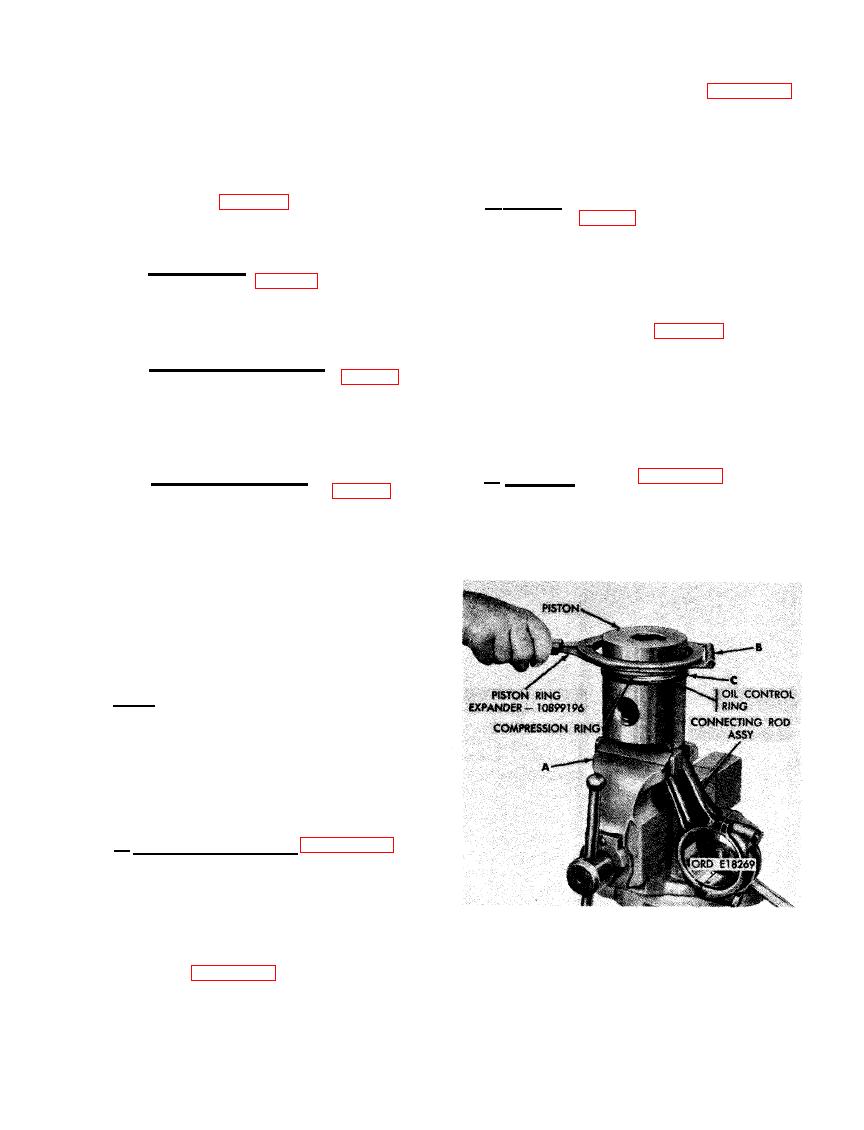
a . Remove Piston Rings. Figure 339. (A)
Place connecting rod and piston assembly in a
soft-jawed vise. (B) Remove top compression
piston r i n g using piston ring expander -
10899196. Remove remaining two compression
rings in same manner. (C) Remove oil control
ring using piston ring expander - 10899196. Re-
move oil control ring expander spring following
PISTON RINGS USING PISTON RING
instructions in figure 340.
EXPANDER - 10899196.
209
|
|
Privacy Statement - Press Release - Copyright Information. - Contact Us |