 |
|||
|
|
|||
|
|
|||
| ||||||||||
|
|
 cylinder head assembly when found unservice-
Note. After the three fuel injector
able.
nozzle and holder assemblies are re-
moved from cylinder head, test nozzle
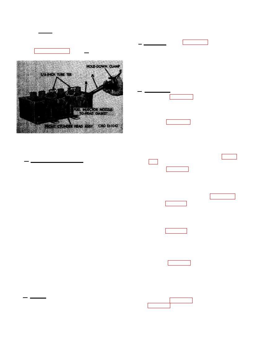
f. Assembly. Refer to figures 193 and 194 and
and holder spray pattern as directed in
reverse the sequence of illustrations and in-
paragraphs 83c and d.
structions to assemble the front cylinder head
assembly. Use a new fuel injector nozzle-to-
head gasket. Hold gasket in place at nozzle end
by applyng a light coating of grease. This in-
sures proper gasket seating and prevents gas -
ket from sliding off end of nozzle and holder
assembly during installation.
g. Installation.
(1) Refer to figures 190 through 192 re-
verse the sequence of illustrations and
instructions to install cylinder head gas-
ket and the front cylinder head assembly
and tighten nuts in the sequence out-
lined in figure 195. Install the new head
gasket properly.
Note. Stud threads must be lubricated
with OE 10 oil to obtain proper torque
reading.
FUEL INJECTOR NOZZLE AND
HOLDER ASSEMBLIES.
(2) Torque tighten front cylinder head nuts
with special wrench as shown in figure
d. Cleaning and Inspection.
(1) Clean cylinder head assembly thor-
(3) Refer to figure 189 and reverse the se-
oughly using dry-cleaning solvent or
quence of instructions to install the
mineral spirits paint thinner. Remove
front set of rocker arms and to connect
hard carbon deposits using a wire brush
fuel injector nozzle fuel return tubes.
or scraper.
(4) Adjust valve clearance following in-
Note. When cylinder head gasket shows
structions which accompany figure 183.
signs of leaking or having been blown,
(5) Refer to figure 62 and reverse the se-
inspect cylinder head closely for dam-
quence of instructions to install front
age.
cylinder head cover gasket and cover.
(2) Inspect cylinder head assembly for
Install new gaskets under cover and
cracks around valve seats and for dam-
breather adapter.
aged gasket surface. Check for evidence
(6) Refer to figures 168 through 172 and re-
of cracked or warped intake and ex-
verse the sequence of illustrations and
haust valves. Replace cylinder head as-
instructions to install the intake, ex-
sembly when cracked or when valve
haust, and cylinder head water outlet
seats show evidence of burning. Check
manifolds as an assembly. Install new
threads on studs and in tapped holes for
manifold gaskets.
good condition. Core hole plugs must be
tight and not show signs of coolant
(7) Refer to figures 44 through 47 and 49
leakage.
through 52 and reverse the sequence
of illustrations and instructions to in-
Note. Thermo fatigue cracks found at
stall the turbosupercharger assembly.
bridge between valve seats are not cause
to reject a head unless coolant leakage
Install new gaskets and check hoses for
serviceable condition. Oil inlet tube and
is evident.
outlet hose connections must be tight.
e. Repair. Replace all studs having stripped
(8) Refer to figure 57, steps C and D and
threads. Repair all damaged threads in tapped
holes using a good used tap. Remove small
quence of instructions to connect fuel
scratches and raised metal from gasket surface
using emery cloth or fine mill file. Replace
injector tubes to nozzle assemblies. Re-
|
|
Privacy Statement - Press Release - Copyright Information. - Contact Us |