 |
|||
|
|
|||
|
Page Title:
CYLINDER HEAD ASSEMBLY OR CYLINDER HEAD GASKET |
|
||
| ||||||||||
|
|
 (3) Adjust valve clearance following in-
(3) Remove front cylinder head cover and
structions for figure 183.
gasket following instructions for fig-
ure 62.
(4) Refer to figure 62 and reverse the se-
quence of instructions to install the front
cylinder head cover. Use new gaskets
(4) Remove intake, exhaust, and cylinder
under cover and breather adapter.
head water outlet manifolds as assem-
blies following instructions in figures
94. CYLINDER HEAD ASSEMBLY OR CYL-
INDER HEAD GASKET
a. General. The front and rear cylinder head
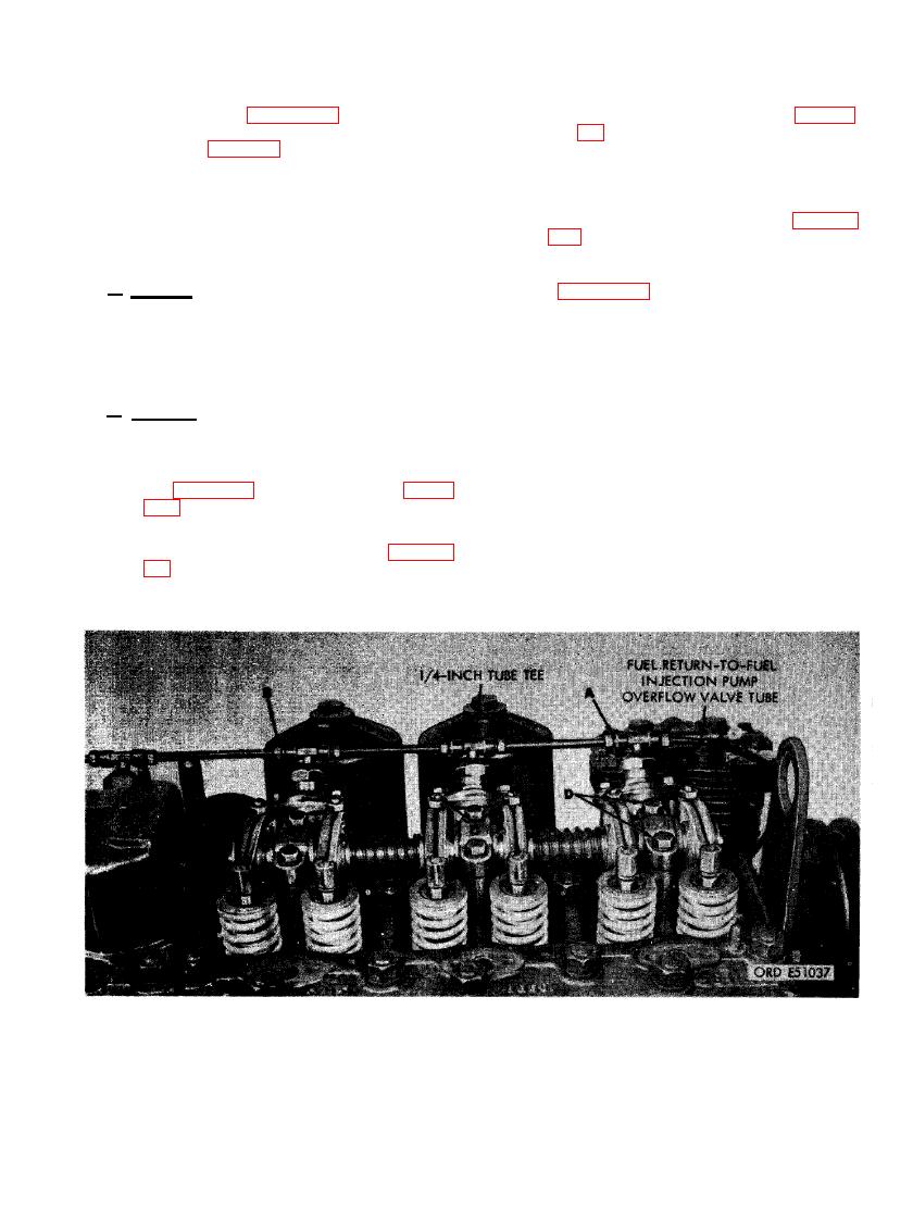
(5) Figure 189. (A) Disconnect 1/4-inch
assemblies are identical and interchangeable.
tube nut on fuel return-to-fuel injection
For instructional purposes the front clyinder
pump overflow valve tube from 1/4-inch
head assembly will be replaced or the cylinder
tube tee in cylinder No. 1 fuel injector
head will be removed for cylinder head gasket
nozzle and holder assembly. (B) Discon-
replacement.
nect the 1/4- inch tube nuts on fuel in-
jector nozzle fuel return tubes from the
b. Removal. Remove cylinder head assembly
1/4- inch tube tee in fuel injector nozzle
as follows.
and holder assembly for cylinder No. 3.
(C) Loosen six valve rocker adjusting
(1) Remove cylinder No. 1, 2, and 3 fuel
screw lock nuts and alternately loosen
injection tubes following instructions
valve rocker adjusting screws to relieve
for figure 57, steps C and D and figure
valve spring tension. (D) Remove six
148, step C.
3/8 x 2-1/2 cap screws and 3/8-inch
(2) Remove turbosupercharger assembly
lock washers securing the front set of
following the instructions for figures
rocker arms to front cylinder head. Re-
move the front set of rocker arms.
REMOVING OR INSTALLING FRONT SET OF ROCKER ARMS.
127
|
|
Privacy Statement - Press Release - Copyright Information. - Contact Us |