 |
|||
|
|
|||
|
|
|||
| ||||||||||
|
|
 using dry- cleaning solvent or mineral
b. Removal. Remove valve rocker arm push
spirits paint thinner. Dry all parts and
rodas follows.
blow out all oil passages in shaft and
rocker arm assemblies using compres-
(1) Remove front cylinder head cover and
sed air. Use a thin wire as a probe to
cover gasket following instructions for
remove heavy gum deposits from oil
passages when necessary.
(2) Remove the front set of rocker arms
(2) Inspect valve rocker arm assemblies
(C) for worn valve stem contact sur-
face and damaged valve rocker arm ad-
justing screw (C- 3). Inspect valve
rocker arm shaft (E) for worn bearing
surfaces, plugged oil passages and evid-
ence of oil leaking past plug (D) at each
end of shaft. Inspect for broken or weak
thrust springs (J). Inspect for cracked
or damaged rocker arm shaft supports
(F). Inspect the valve rocker arm re-
taining ring (A) for weakness or distor-
tion. Inspect rocker arm thrust washer
(B) for excessive wear or distortion.
e. Repair. Replace unserviceable parts.
f. Assembly. Refer to figures 184 through
186- and reverse the sequence of illustrations
and instructions to assemble the front set of
rocker arms.
g. Installation.
(1) Refer to figures 180 and 181 and re-
verse the sequence of illustrations and
instructions to install the front set of
rocker arms. Do not tighten valve
rocker arm adjusting screw lock nuts
until valve clearance has" been adjusted.
(2) Adjust valve clearance following in-
structions for figure 183.
(3) Refer to figure 62 and reverse the se-
quence of instructions to install the
front cylinder head cover. Use new
head cover gaskets and
cylinder
breather adapter gaskets.
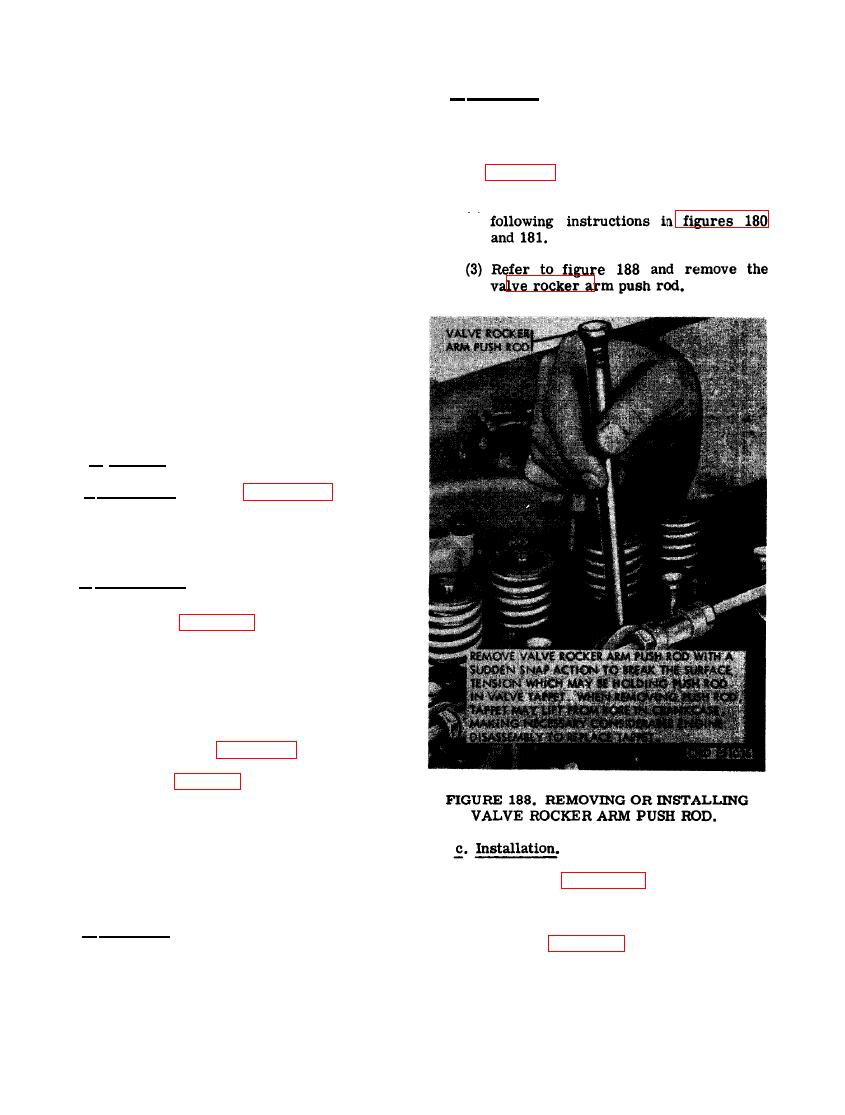
(1) Refer to figure 188 and install valve
rocker arm push rod. Push rod must
seat properly in valve tappet.
a. General. Each of the 12 valve rocker arm
(2) Refer to figures 180 and 181 and re-
push rods is removed in the same manner. For
verse the sequence of illustrations and
instructional purposes, the push rod for cylinder
instructions to install the f rent set of
No. 2 exhaust valve rocker arm assembly will
rocker arms.
be removed.
126
|
|
Privacy Statement - Press Release - Copyright Information. - Contact Us |