 |
|||
|
|
|||
|
Page Title:
INSTALLATION OF ENGINE ACCESSORIES |
|
||
| ||||||||||
|
|
 degree elbow in fuel filter overflow
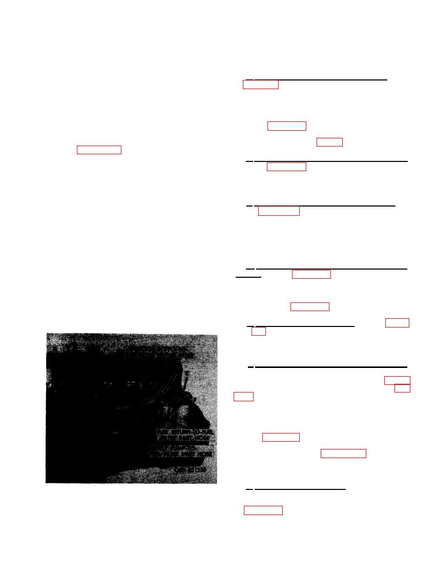
286. INSTALLATION OF ENGINE ACCES-
return tee. (G) Install cushioned clamp
SORIES
around injector supply-to-fuel filter
outlet hose and fuel return- to- fuel filter
a. Install Air Compressor Assembly. Refer
inlet hose and secure clamp to crank-
to figures 81 through 83 and reverse the sequence
case with 3/8 x 3/4 cap screw and 3/8-
of illustrations and instructions to install the
inch lock washer. (H) Install cushioned
air compressor assembly and air compressor
clamp around supply pump-to- fuel filter
drive belt. Use a new gasket. Adjust air com-
inlet hose and secure clamp to crank-
pressor drive belt deflection following instruc-
case with 3/8 x 3/4 cap screw and 3/8-
tions for figure 87. Connect fuel return-to-fuel
inch lock washer.
inject ion pump overflow valve tube to fuel in-
jection pump (Refer to fig. 57, step B).
(2) Figure 512. (A) Connect fixed end of
25- inch long fuel supply pump-to-fuel
b. Install Flame Heater Fuel Pump Assembly.
filter inlet hose in the fuel filter inlet
Refer to figure 78 and reverse the sequence of
elbow. (B) Connect swivel end to fuel
instructions to install the flame heater fuel
supply pump outlet 45 degree elbow.
pump.
(C) Connect fixed end of injector supply-
to-fuel filter outlet hose to 90 degree
c. Install Turbosupercharger Assembly. Re-
elbow in fuel filter outlet. (D) Connect
fer to figures 44 through 53 and reverse the
the swivel end to the connector in the
sequence of illustrations and instructions to in-
fuel injection pump hydraulic head.
stall the turbosupercharger assembly. Install
(E) Connect fixed end of fuel return-
new gaskets and tighten oil inlet tube and oil
to-fuel filter inlet hose to overflow
outlet hose connections securely.
valve in injection pump hydraulic head.
(F) Connect the swivel end to the fuel
filter overflow return tee. (G) Install
d. Install Generator Assembly and Drive
cushioned clamp over all three fuel
Belts. Refer to figures 41 and 42 and reverse
hoses. (H) Install cushioned clamp on
the sequence of illustrations and instructions
fuel injection pump bracket stud and
to install the generator assembly. Adjust engine
secure with one 1/4- inch lock washer
fan and generator drive belt deflection following
and 1/4- inch plain nut.
instructions for figure 43.
e. Install Starter Assembly. Refer to fig-
ures 39 and 40 and reverse the seauence of
illustrations and instructions to install the
starter assembly using new starter gasket.
f. Remove Engine From Overhaul Stand.
Hook engine lifting sling -8715107 to front and
rear engine lifting brackets as shown in figure
223. Install spreader -10912586 in sling (fig.
engine weight is supported by sling. Remove
5/8- inch plain nut, and 5/8 x 1-3/4 cap screw
securing each engine mounting bracket to cradle
-7950198 of engine overhaul stand -7950189.
Refer to figure 296, step A and follow the in-
structions to remove front mounting brackets
from engine. Refer to figure 295, step A and
follow the instructions to remove the rear
mounting brackets from the engine.
g. Test and Adjust Engine. After the engine
has been completely assembled, the engine
should be run in, tested, and adjusted as directed
in Chapter 9.
(EARLY MODEL ENGINES).
325
|
|
Privacy Statement - Press Release - Copyright Information. - Contact Us |