 |
|||
|
|
|||
|
Page Title:
FIGURE 79. FLAME HEATER FUEL PUMP ASSEMBLY |
|
||
| ||||||||||
|
|
 Caution: The electrical system in the
flame heater fuel pump is negative
grounded. "A" pin is positive, and "B"
pin in negative. Do not reverse polarity
during checking or installation. Reverse
polarity will cause permanent damage
to the pump.
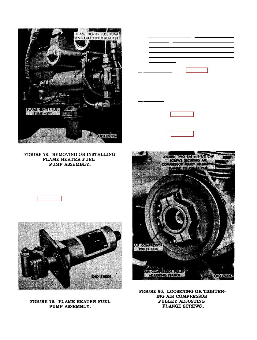
b. Installation. Refer to figure 78 and re-
verse the sequence of instructions to install the
flame heater pump assembly.
a. Removal. Remove the air compressor as-
sembly as follows.
(1) Refer to figure 80 and loosen the air
compressor pulley adjusting flange cap
screws.
(2) Refer to figure 81 and loosen the air
compressor pulley adjusting flange.
chine screws securing fuel pump as-
sembly to flame heater fuel pump and
fuel filter bracket. (G) Remove flame
heater fuel pump assembly.
(2) Figure 79 illustrates the flame heater
fuel pump after removal from the en-
gine.
78
|
|
Privacy Statement - Press Release - Copyright Information. - Contact Us |