 |
|||
|
|
|||
|
Page Title:
FLAME HEATER FUEL PUMP ASSEMBLY |
|
||
| ||||||||||
|
|
 Mark on crankshaft damper and pulley
assembly must be alined with pointer
on timing gear cover (fig. 66).
Both the intake and exhaust valves
must be closed (fig. 63).
The mark on fuel injection pump
automatic advance hub must be alined
with pointer (fig. 64) and the marked
tooth on plunger drive gear must be
visible through timing window (fig. 65).
When timing marks on fuel injection
pump and engine are not alined remove
fuel injection pump driven gear retain-
ing plate and gear following the in-
structions which accompany figures
timing (c (4) and (5) above) and repeat
step (2) above.
(4) Secure Fuel Injection Pump Driven
Gear. Tighten cap screws securing fuel
injection pump driven gear and driven
gear retaining plate as follows.
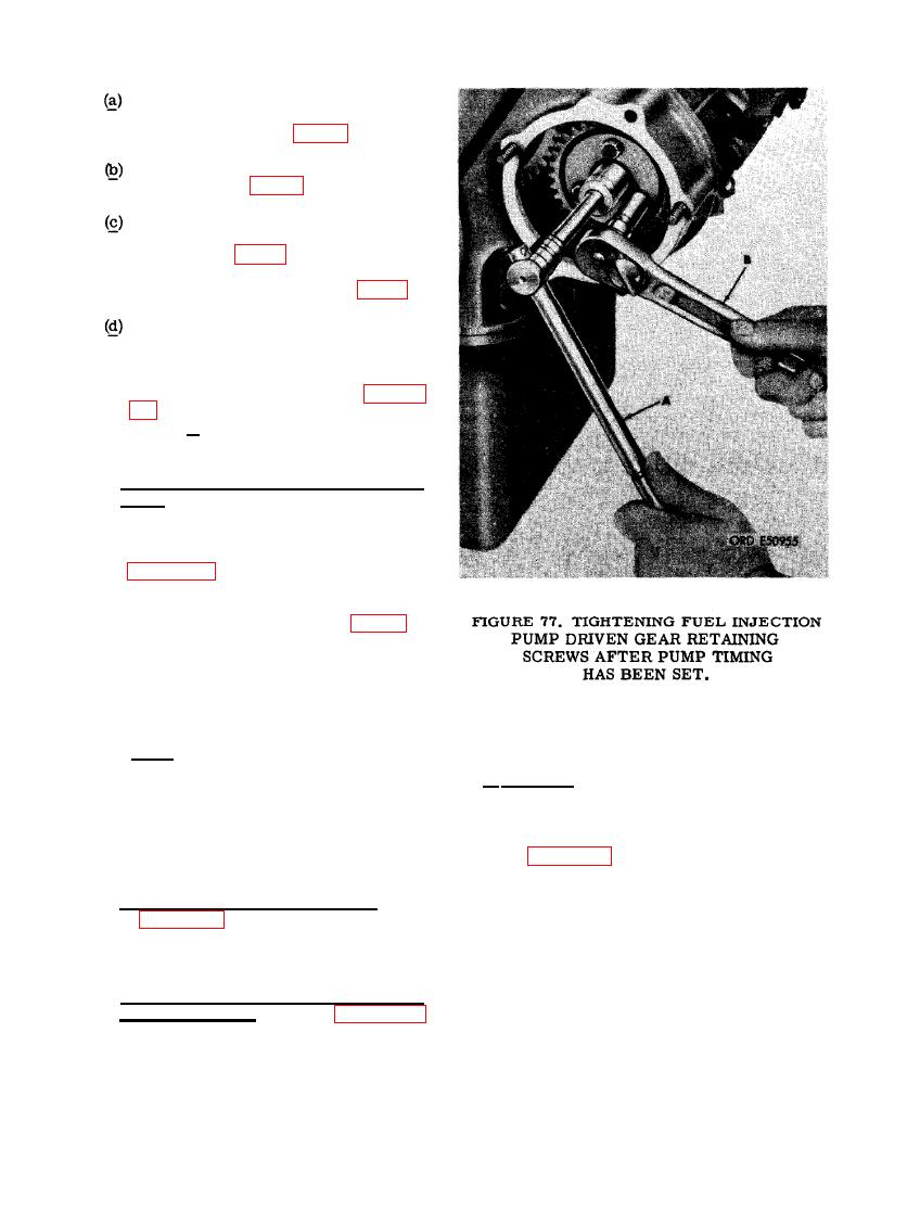
(5) Figure 77. (A) Rotate fuel injection
pump automatic advance unit shaft as
necessary in either direction until mark
on hub alines with pointer (fig. 64).
Hold shaft in alined position. (B) Tighten
three 3/8 x 1-1/4 cap screws to a torque
of 275 to 325 pound inches to secure
fuel injection pump driven gear and re-
taining plate.
64. FLAME HEATER FUEL PUMP ASSEMBLY
Note. The three elongated bolt holes in
fuel injection pump driven gear (fig.
a. Removal. Remove flame heater fuel pump
67) allow about 20 degrees free rotation
assembly as follows.
around the injection pump driven gear
hub. In extreme cases, remove the
driven gear retaining plate and driven
gear to reposition the gear on the hub.
(1) Figure 78. (A) Disconnect flame heater
fuel inlet solenoid valve-to-flame heat
fuel pump, tube from 1/4 tube x 1/8 pipe,
(6) Install front cylinder head cover. Refer
90 degree elbow. (B) Remove 1/8 pipe
to figure 62 and reverse the sequence
adapter and 1/4 tube x 1/8 pipe, 90 de-
of instructions to install the front cyl-
gree elbow from flame heater fuel pump.
inder head cover.
(C) Disconnect flame heater fuel pump-
to-flame heater nozzle tube from adap-
ter in fuel pump. (D) Remove 1/8 tube
(7) Complete installation of fuel injection
x 1/8 pipe union from fuel pump. (E)
pump assembly. Refer to figures 56
Disconnect flame heater harness from
through 61 and reverse the sequence of
receptacle connector at rear of pump.
illustrations and instructions to com-
(F) Remove two No. 10 plain nuts, No.
plete installation of the fuel injection
10 lock washers, and No. 10 x 7/8 ma-
pump assembly.
77
|
|
Privacy Statement - Press Release - Copyright Information. - Contact Us |
