 |
|||
|
|
|||
|
Page Title:
Section VI. REBUILD OF MISCELLANEOUS ENGINE COMPONENTS |
|
||
| ||||||||||
|
|
 c. Installing Piston Oil Control Ring and No.
3 Compression Ring.
(1) Refer to figure 340 and install oil control
expander spring as shown.
(2) Refer to figure 339 and install oil control
ring u s i n g piston ring expander -
10899196.
(3) Refer to figure 339 and install No. 3
compression ring using piston ring
expander - 10899196.
N o t e . No. 3 compression ring is
marked "TOP" on one face and this
side is installed toward head of piston.
The face of the ring is tapered as shown
in figure 344. The other piston rings
are not marked.
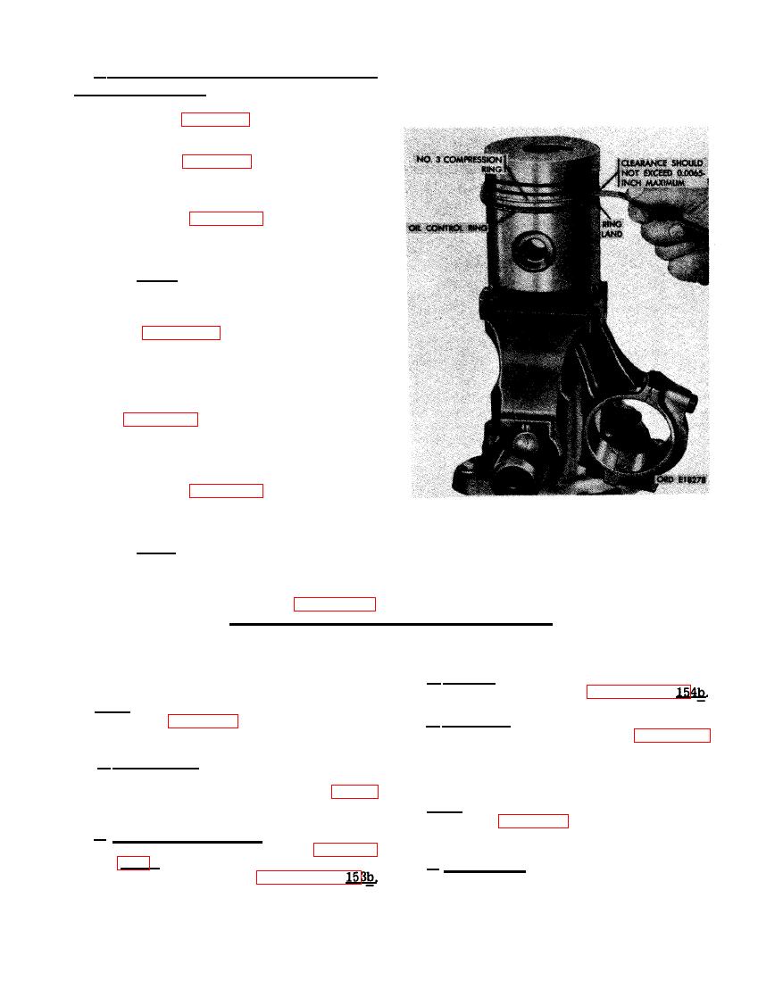
(4) Check No. 3 compression ring clear-
ance between ring and ring land on
piston using a feeler gage as shown in
0.0065-inch. When excessive clearance
exists, piston ring lands are worn and
piston should be replaced.
(5) Refer to figure 339 and install No. 1
and No. 2 compression rings as shown
using piston ring expander - 10899196.
N o t e . The clearance between No. 1
and No. 2 compression rings and ring
SION RING CLEARANCE USING A
lands on piston cannot be accurately
FEELER GAGE.
checked because piston rings and ring
grooves are tapered. See figure 344.
Section VI. REBUILD OF MISCELLANEOUS ENGINE COMPONENTS
c . Repair. Repair crankshaft rear oil seal
housing (DD) as directed in paragraph
Note. The key letters shown below in paren-
theses refer to figure 322 except where other-
d. Assembly. Install new crankshaft rear oil
wise indicated.
seal (CC) following instructions for figures 166
and 167.
a. Disassembly. Remove crankshaft rear oil
seal (CC) from oil seal housing (DD) using a
suitable drift following instructions for figure
165. Discard seal.
Note. The key letters shown below in paren-
theses refer to figure 322 except where other-
b. Cleaning and Inspection. Thoroughly clean
wise indicated.
crankshaft rear oil seal (CC) as directed in para-
graph 152e. Inspect crankshaft rear oil seal
a. Disassembly. Disassembly of the air com-
housing (DD) as directed in paragraph
pressor support assembly (B) is limited to re-
215
|
|
Privacy Statement - Press Release - Copyright Information. - Contact Us |