 |
|||
|
|
|||
|
Page Title:
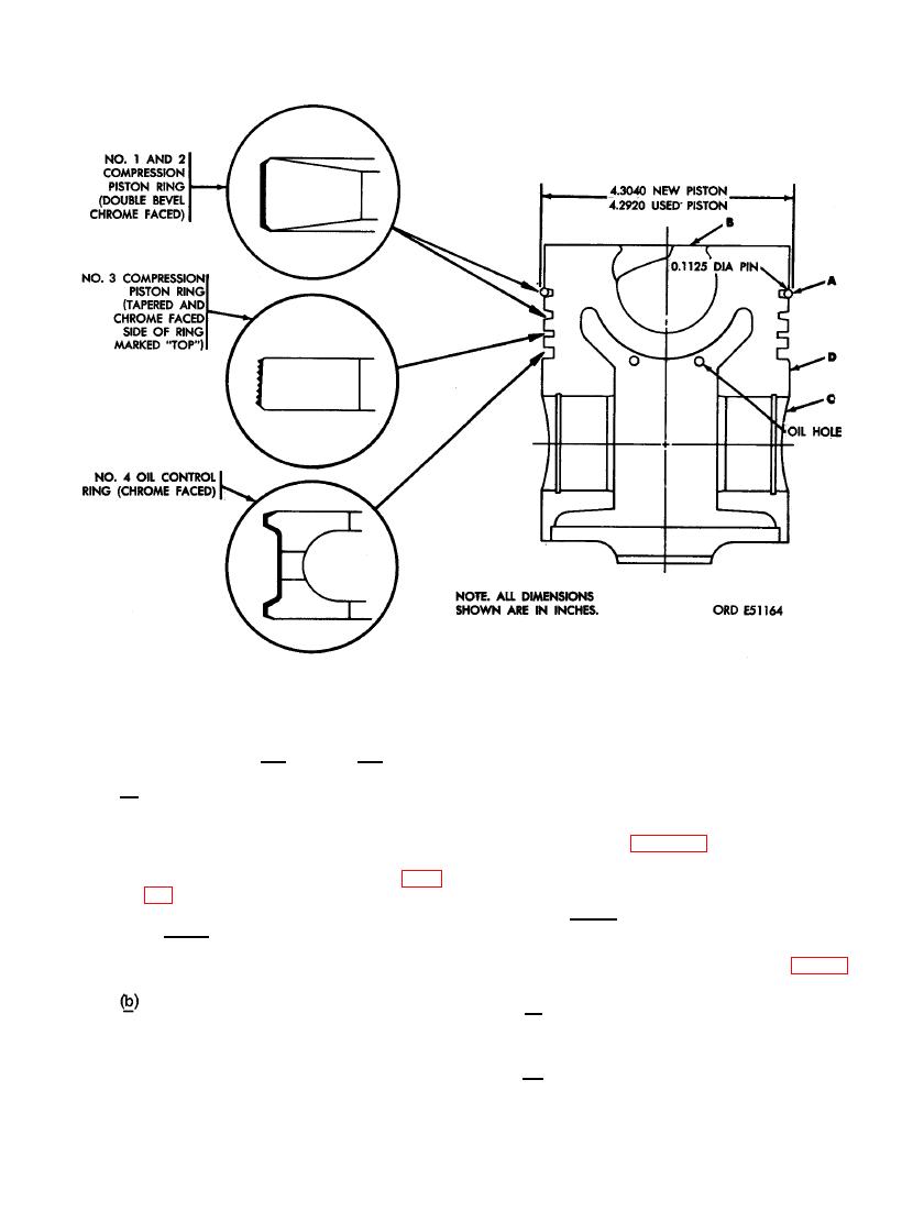
FIGURE 344. INSPECTION POINTS FOR PISTON. |
|
||
| ||||||||||
|
|
 be sticking in piston ring grooves. Check
lower rings using a feeler gage. Push
side clearance of rings in piston grooves
rings into groove as far as possible
as described in (a) through (d) below.
and insert feeler gage, by trial, until
one is found that will enter this area
(a) Check side clearance (ring width) on
with a slight drag. Check the thickness
No. 1 and 2 top compression rings by
dimensions of this gage against the
measuring the thickness of the ring
limits specified in repair and rebuild
at the outer edge. Check the dimen-
standards (par. 292). Mark all rings
sion against the limits specified in
for replacement that are not within
repair and rebuild standards (par.
limits specified.
Note. The third compression ring
Note. These rings must be checked
and oil control ring side clearance
must also be checked after rings are
i n this manner because they are
tapered.
installed on piston as shown in fig-
ure 348.
The side clearance of the third com-
(c) E x c e s s i v e side clearance may be
pression ring and oil control ring can
caused by the rings being worn or
be checked by installing them in their
by piston ring groove wear.
proper locations on the piston using
piston ring expander - 10899196. Mea-
(d) Less than normal clearance indicates
sure the side clearance of these two
a broken or damaged ring land.
212
|
|
Privacy Statement - Press Release - Copyright Information. - Contact Us |