 |
|||
|
|
|||
|
|
|||
| ||||||||||
|
|
 d. Connecting Rod Sleeve Bearing Halves.
(4) Replace piston if oil holes in ring lands
Replace all connecting rod sleeve bearing halves
cannot be cleared or if lands are dam-
(SS-4) that do not check within limits specified
aged or broken.
in repair and rebuild standards (par. 292) or
when bearings do not show at least 75 percent
(5) Replace pistons which are badly burred,
contact by Prussian blue transfer after bore
nicked, or scratched. Remove minor
check (par. 174b(5), above).
burs, nicks, or scratches from pistons
with crocus cloth dipped in dry-cleaning
solvent or mineral spirits paint thniner.
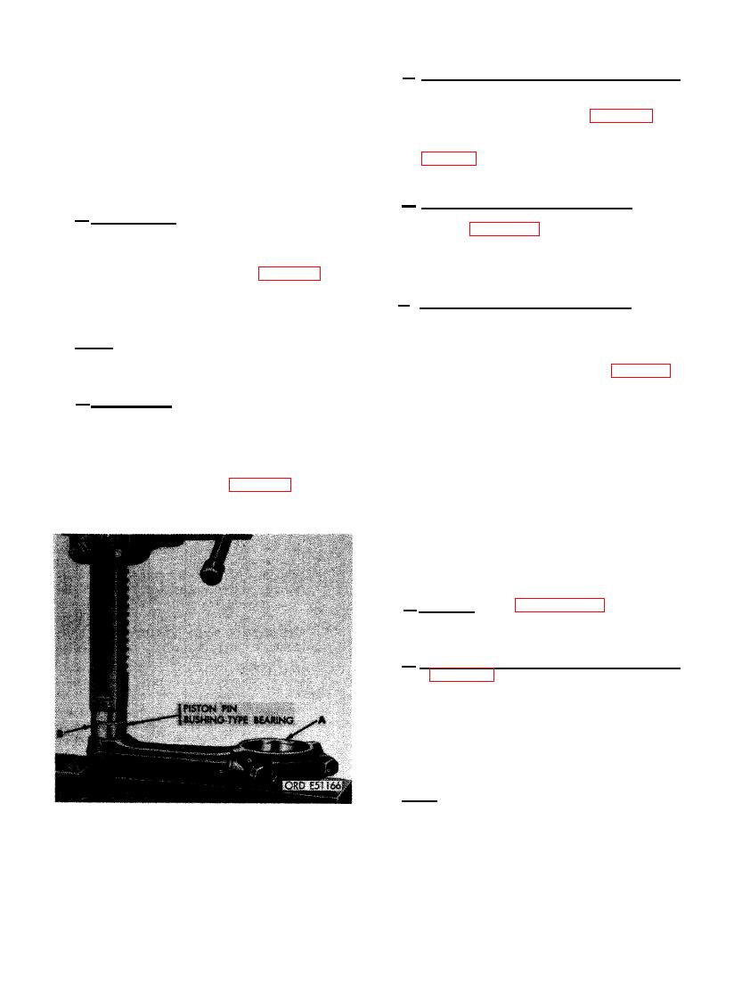
e . Piston Pin Bushing-type Bearings. Re-
place worn or damaged piston pin bushing-type
b. Piston Rings. Replace rings (SS, TT, and
bearing (SS-1). Figure 347. (A) Position con-
UU) that are scuffed, scored, chipped, or
necting rod on suitable supports as shown. Bore
scratched or when they show signs of abrasion.
new bushing to 1.6265 to 1.6267-inches.
Replace rings when not within limits specified
in repair and rebuild standards (par. 292) for
side clearance in piston grooves and for end
f. Connecting Rods, Caps, and Bolts.
gap. Replace oil control rings if oil drain holes
cannot be cleaned.
(1) Replace connecting rod assemblies (SS)
Note. Piston rings cannot be repaired. If a
which are not within limits specified in
ring must be replaced, replace all rings on that
repair and rebuild standards (par. 292).
piston.
Rods with damaged piston pin bushings
c . Piston Pins. Replace piston pins (XX)
can be repaired as outlined in e above.
w h i c h are cracked or have deep nicks or
scratches. Remove minor nicks or scratches
(2) Replace rod cap bolts (SS-6) that have
with crocus cloth dipped in dry-cleaning solvent
damaged threads.
or mineral spirits paint thinner. Replace piston
pins which are not within limits specified in re-
pair and rebuild standards (par. 292). Replace
(3) Replace b o l t s that are cracked,
cracked or damaged piston pin retaining rings
scratched, or that show any evidence
(WW).
of stretching.
176. ASSEMBLY
a . General. Refer to paragraph 156 for as-
sembly instructions.
b. Assemble Pistons and Connecting Rods.
Refer to figures 341 and 342 and reverse the se-
quence of illustrations and instructions to as-
semble the piston and connecting rods. The
number stamped on top of piston, must cor-
respond with numbers marked on connecting rod
and rod cap. The number on piston must be on
the same side as rod marks.
Note. Lubricate piston pins, piston pin bore
in piston, and piston pin bushing-type bearing
in connecting rod with engine oil OE-10 (MIL-
0-2104) during assembly.
PISTON PIN BUSHING-TYPE BEARING.
214
|
|
Privacy Statement - Press Release - Copyright Information. - Contact Us |