 |
|||
|
|
|||
|
Page Title:
Section II. REBUILD OF CYLINDER AND CRANKCASE ASSEMBLY |
|
||
| ||||||||||
|
|
 156. ASSEMBLY INSTRUCTIONS
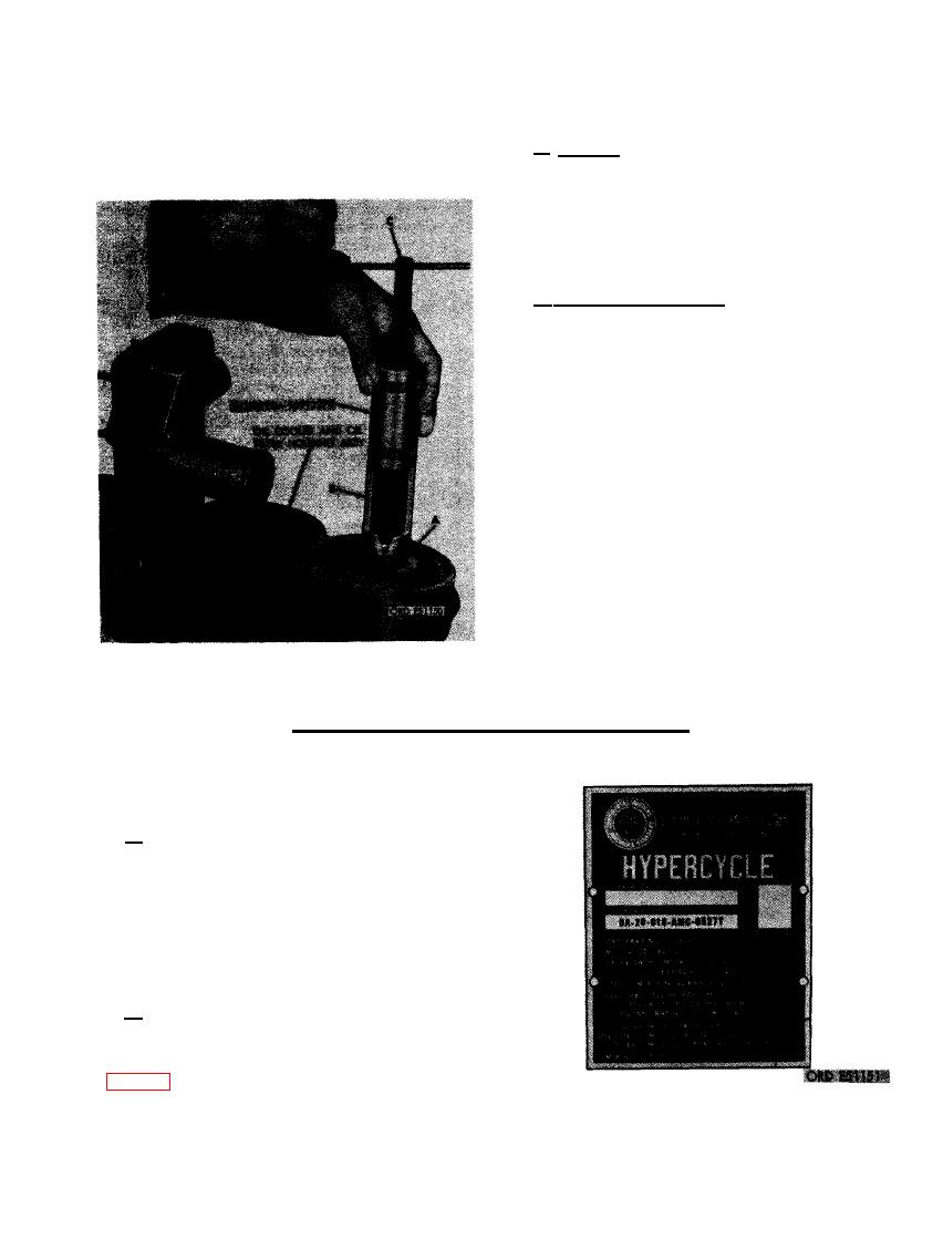
serter resting solidly against the hous-
ing as shown. (C) Slowly turn handle
of pilot clockwise until no further re-
a. General. Extreme care must be exercised
sistance is felt. The insert will then be
in all component assembly operations to insure
flush with housing. Remove the inserter.
satisfactory engine performance. General rules
for assembly are outlined below. Step-by-step
procedures for assembling the various com-
ponents are covered in the paragraph relating
to the specific component.
b . Precautionary Rules.
(1) Cleanliness is essential in all component
assembly operations. Dirt and dust, even
in minute quantities, are abrasive. Parts
must be cleaned as specified and kept
clean. Wrap or cover parts and com-
ponents when assembly procedures are
not immediately completed.
(2) Coat all bearings and all contact sur-
faces with engine oil OE-10 (MIL-0-
2104) to insure lubrication of parts
during initial engine starting.
(3) Replace all gaskets and preformed pack-
ings removed in disassembly.
(4) Some screws and bolts in this engine
are fabricated with nylon inserts in the
threaded end. This type of screw does
INSERT IN OIL COOLER AND OIL FIL-
not require additional locking devices.
TER HOUSING.
Section II. REBUILD OF CYLINDER AND CRANKCASE ASSEMBLY
157. GENERAL
a . This section covers disassembly, clean-
ing, inspection, repair, and assembly of the
cylinder and crankcase assembly and its re-
lated parts. The related parts are those that
are machined with the crankcase, and removed
during engine disassembly. The main bearing
caps and cylinder sleeves are included in this
group along with other miscellaneous items.
b . During rebuild of the engine and com-
ponents, replacement parts will be needed. For
engine model identification, and ordering re-
placement parts, note the engine name plate
crankcase and cylinder block.
193
|
|
Privacy Statement - Press Release - Copyright Information. - Contact Us |