 |
|||
|
|
|||
|
Page Title:
Installation of Overflow Valve Assembly |
|
||
| ||||||||||
|
|
 TM 9-2910-226-34
NOTE
If the injection pump is to be tested after
assembly, do not tighten the overflow valve
or plastic tubing until the fuel leakage and
timing check as described in paragraphs 3-50
through 3-58 has been performed.
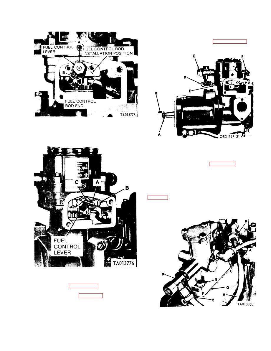
Figure 3-150. Installing fuel control unit assembly on metering
and distributing fuel injection pump.
Figure 3-152. Installing overflow valve assembly
3-46. Installation of Fuel Density Compensator. a.
Installation of Fuel Density Compensator (Code B,
tion a new mounting gasket (G) on governor
housing. Position fuel density compensator on
governor housing and secure with four x 1
capscrews (E) and four inch lockwashers (F).
Torque tighten screws 50-60 inch-pounds. Install
density compensator to overflow valve tubing (E,
tubing (H) to tee (D) and elbow in hydraulic head
(B).
Figure 3-151. Installng control unit retainer.
3-45. Installation of Overflow Valve Assembly. a.
selection of the proper overflow valve assembly.
washer (A) and stet nut (B) on advance unit shaft.
Tighten nut finger tight. Install overflow valve
assembly (C) in position on hydraulic head.
Figure 3-153. Installing fuel density compensator assembly.
3-87
|
|
Privacy Statement - Press Release - Copyright Information. - Contact Us |
