 |
|||
|
|
|||
|
Page Title:
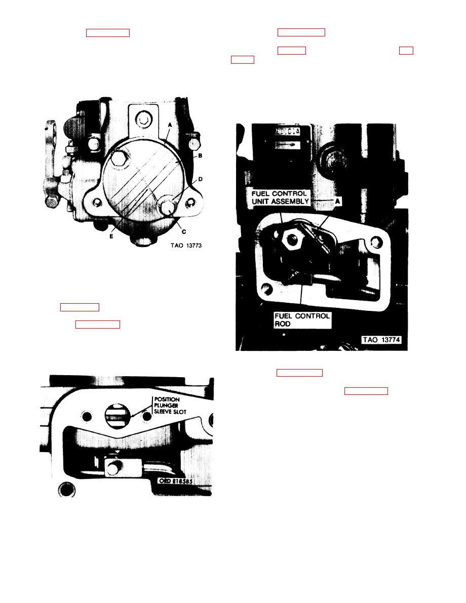
Installation of Fuel Control Unit Assembly |
|
||
| ||||||||||
|
|
 TM 9-2910-226-34
(5) Refer to figure 3-147. Coat end cap gasket with
assembly with new preformed packing, so that plunger
a thin coat of er, MIL-S-45180 on side facing end cap.
sleeve pin (A, fig. 3-47) engages plunger sleeve slot (fig.
Install end cap gasket (A) and governor end cap (B) and
secure with two machine screws (C) and lockwashers
and forth. Lever should move through about a 500 angle
(D). Torque tighten screws to 50-60 inch-pounds and se-
between and below retainer mounting holes. If this
cure with locking wire (E).
movement occurs, pin is engaged in sleeve slot. If not,
remove and reinstall control unit and engage plunger
sleeve pin in plunger sleeve slot.
Figure 3-147. Installing governor end cap.
3-44. Installation of Fuel Control Unit
Assembly
NOTE
See figures 3-48, 3-49 and 3-50 for iden-
tification of control units.
at bottom of travel, as shown, by pressing down on
sleeve. The fuel control unit lever must be in an idle
position before inserting plunger sleeve pin into plunger
sleeve slot.
Figure 3-149. Correct installation of control unit in plunger sleeve dot.
C.
Refer to figure 3-150. Aline the control rod end
with the hole in the control unit lever (A) and install re-
taining pin (B) as shown. Refer to figure 3-151, Install
control unit retainer (A) and secure with two assembled
washer screws (B). Torque tighten screws to 18-23
inch-pounds. Clearance between retainer and control
unit shaft must be .0100 to .0250 inches. Secure screws
with locking wire (C).
NOTE
Operate fuel control lever back and forth
while looking through the overflow valve
discharge hole in the hydraulic head. If the
plunger sleeve is moving, the sleeve pin has
remained properly engaged in the plunger
sleeve slot.
Figure 3-148. Location of plunger sleeve slot.
3-86
Change 2
|
|
Privacy Statement - Press Release - Copyright Information. - Contact Us |
