 |
|||
|
|
|||
|
Page Title:
Inspection of Overflow Valve Assembly |
|
||
| ||||||||||
|
|
 TM 9-2910-226-34
damage can be repaired with a used tap or die.
Replace all threaded parts that are beyond repair.
3-19. Inspection of Overflow Valve Assembly.
Inspect the overflow valve threads for damage and
inspect valve for cracks. Replace the complete
overflow valve assembly if damaged. Refer to figures
3-38, 3-39 and 3-40 for selection of replacement
Fuel Supply Pump
Fuel Injection Pump
overflow valves. Both used and new valves will be
4320-908-6322
Code A (2910 -178-1 115)
functionally inspected at pump calibration and test
4320-908-6321
Code B (2910-908-6320)
as outlined in paragraph 3-58b.
4320-908-6321
Code C, D and E (2910-759-5410)
4320-999-2276
Code F (2910-017-9778)
2910-871-5428 or
Code G (early, late and rebuild,
4320-908.6321.
(2910-860-2333 or 2910-966-6317).
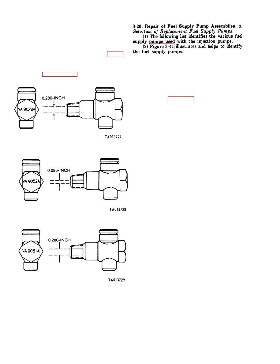
(3) Refer to figure 3-41 to distinguish the fuel
supply pump identifying features.
(a) Supply pump 4320-908-6322 has relief
valve in pump gear cover and relief valve housing is
stamped 80 PSI.
(b) Supply pump 4320-908-6321 has a flat
pump gear cover and check valve screw has -NPT
tapped hole.
(c) Supply pump 320-999-2276 has relief
Figure 3-38. Overflow valve assembly (code A. B, C, D
valve in pump gear cover and relief valve housing is
and E pumps).
stamped 60 PSI.
(d) Supply pump2910-871-5428 has a flat
pump gear cover and check valve screw does not
have tapped hole.
Figure 3-39. Overflow valve assembly (code F pump).
Figure 3-40. Overflow valve assembly (code G pump).
3-30
|
|
Privacy Statement - Press Release - Copyright Information. - Contact Us |
