 |
|||
|
|
|||
|
|
|||
| ||||||||||
|
|
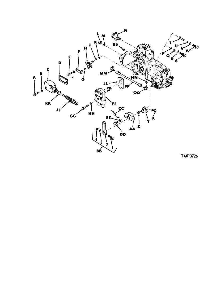 TM 9-2910-226-34
A x1 fillister head screw.
Y Operating lever stop
B -inch lockwasher
Z Retaining ring
C Timing window cover
AA Upper dust cover
D Timing window cover gasket
BB Operating lever assembly
1 Lever clamping screw
E Assembled washer screw
F Control unit retainer
2 Operating lever
G Retaining pin
3 -inch lockwasher
H Fuel control unit assembly
4 -inch nut
J Plunger sleeve pin
CC Governor lead seal
K Preformed packing
DD No. 12x3/8 machine screw
L 9/16-inch plain nut
EE No. 12 lockwasher
FF Fuel supply pump assembly
M 9/16-inch lockwasher
N Overflow valve assembly
GG x1 machine screw
P Preformed packing
HH -inch lockwasher
Q Oil filter
JJ Fuel shut-off rod assembly
R Filter screw copper gasket
KK Shutoff rod gasket
S Oil filter screw
LL Fuel supply pump gasket
T Pin
MM Pipe to tube tee
U Preformed packing
NN Pipe nipple
V Gasket
PP Oil hose assembly
W Screw
QQ 90 elbow
X Operating lever stop screw
RR Woodruff key
Figure 3-37. Code F and G injection pump assemblies, partial exploded view.
3-18. Cleaning and Inspection. a. Cleaning. Immerse
passages thoroughly. Refer to TM 9-214 for care and
and clean all parts in dry-cleaning solvent,
maintenance of antifriction bearings.
specifications PS-661, and dry with compressed air.
b. Inspection and Repair. Examine all threaded
Cover parts with a clean lint-free cloth and keep all
parts for worn or damaged threads. Minor thread
parts clean until assembly. Clean all fuel and oil
3-29
|
|
Privacy Statement - Press Release - Copyright Information. - Contact Us |
