 |
|||
|
|
|||
|
Page Title:
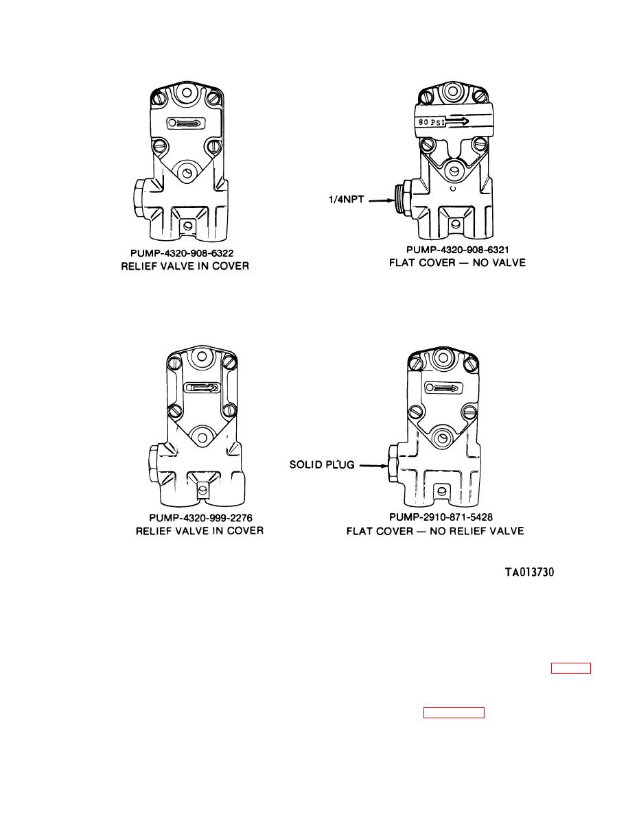
Figure 3-41. Fuel supply pump identification. |
|
||
| ||||||||||
|
|
 TM 9-2910-226-34
Figure 3-41. Fuel supply pump identification.
NOTE
c. Inspection.
Components of the fuel supply pump
(1) Inspect the pump housing for cracks, thread
assemblies are not spare part items except
darn age, loose idler gear pin (R), or other evidence of
for a seal repair kit 2910-489-5994. Perform
fuel leakage. If the threads cannot be repaired using
the following test and inspection to deter-
a suitable thread tap, replace the complete assembly.
mine if the supply pump is serviceable, needs
(2) Inspect the fuel pump drive gear (B) fig. 3-43
a seal kit or needs replacement.
for evidence of wear or other damage. Replace the
b. Test. Plug all openings except the fuel inlet.
complete pump assembly if either condition exists.
Using an auxiliary fuel supply, pressurize pump to
d. Installation of the Seal Repair Kit.
60 psi minimum, and examine for fuel leaks, paying
(1) Refer to figure 3-42. Remove four fillister
head screws (A), lockwashers (B) and housing cover
particular attention to the pump housing oil seal. If
the housing oil seal leaks, install the seal repair kit as
(C).
outlined in step d. below.
3-31
|
|
Privacy Statement - Press Release - Copyright Information. - Contact Us |