 |
|||
|
|
|||
|
Page Title:
Figure 3-42. Removing or installing housing cover. |
|
||
| ||||||||||
|
|
 TM 9-2910-226-34
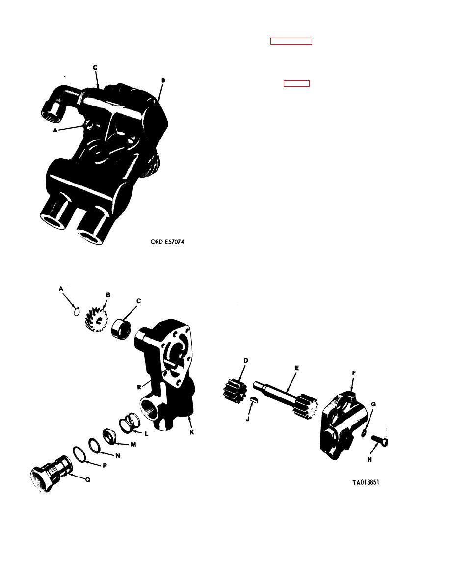
(2) Refer to figure 3-43. Remove retaining ring
(A) using suitable pliers. Remove camshaft drive
gear (B), Woodruff key (J), drive shaft (E), and idler
gear (D). Remove and discard housing oil seal (C).
KEY to fig 3-43
A Retaining ring
B Fuel pump drive gear
C Housing oil seal
D Idler gear
E Drive shaft
F Housing cover
G 3/16-inch lockwasher
H 3/16x1/2 fillister head screw
J Woodruff key
K Pump housing
L Check valve spring
M Check valve
N Valve screw gasket
P Preformed packing
Q Valve screw
R Idler gear pin
Figure 3-42. Removing or installing housing cover.
Figure 3-43. Fuel supply pump, exploded view.
3-32
|
|
Privacy Statement - Press Release - Copyright Information. - Contact Us |