 |
|||
|
|
|||
|
Page Title:
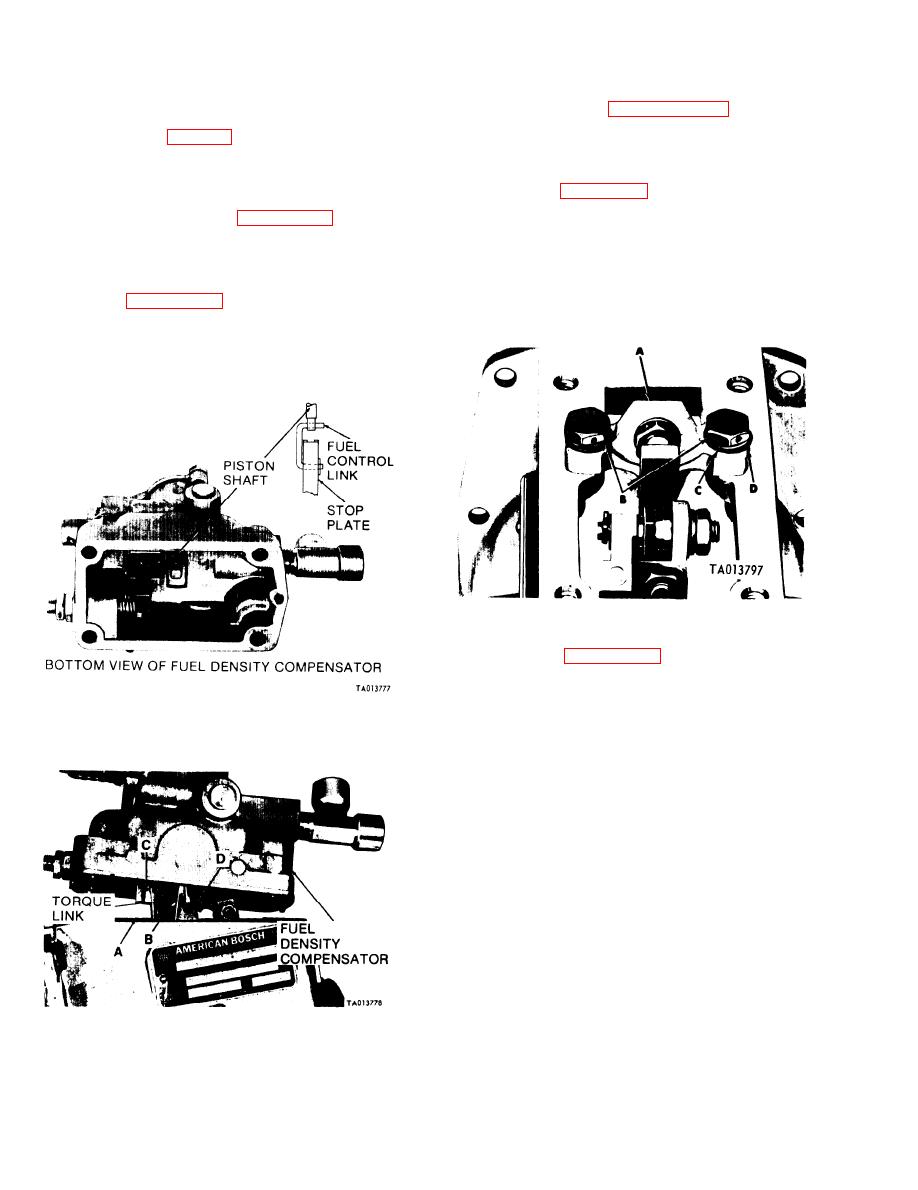
Figure 3-154. installing stop plate and link assembly (Code A pumps}. |
|
||
| ||||||||||
|
|
 TM 9-2910-226-34
CAUTION
c. Tamper Proof Cover. Do not install tamper
Care should be exercised during installation
proof covers. They will be installed after test and
of the compensator on code A pumps. The
adjustment of pump in paragraphs 3-50 through 3-
top of the fuel control link is not secure to the
58.
piston shaft (fig. 3-154). If the top of the link
d . Installation of Stop Plate and Bridge
does not remain engaged in the shaft, the
Assembly and Governor Housing Cover (code G
stop plate will fall into the governor housing,
pumps).
causing serious damage to the pump.
(1) Refer to figure 3-156. Install plate and bridge
b. Installation of Fuel Density Compensator
assembly (A) on governor housing and secure with
two capscrews (B), lockwashers (C), and flat washers
new mounting gasket (A) on governor housing.
(D). Torque tighten screws to 50-60 inch-pounds.
Engage dovetail in torque link stop (B) with
NOTE
dovetails on guide (C) and compensator plate (D).
The plate and bridge assembly is installed
All divetails must be properly engaged. Refer to a
over the rear pair of tapped holes in the
above and figure 3-153 to complete installation of
governor housing.
compensator on injection pump.
NOTE
The stop furnished with a compensator is to
be used with the compensator.
Figure 3-156. Installing plate and bridge assembly on governor
housing (code G pumps).
(2) Refer to figure 3-157. With throttle lever
secured in full fuel position, insert a feeler gage (A)
between the stop plate (B) and smoke limit cam (C)
and adjust locknuts (D) of droop plate screw to
Figure 3-154. installing stop plate and link assembly
obtain a preliminary adjustment clearance of 0.020-
(Code A pumps}.
inch .
Figure 3-155. Assembling fuel density compensator fuel stop
plates (Code A pumps).
3-88
|
|
Privacy Statement - Press Release - Copyright Information. - Contact Us |
