 |
|||
|
|
|||
|
|
|||
| ||||||||||
|
|
 *TM 9-2815-213-34
ward position. Refer to Paragraph 3-43.
a. Install injector push rod in no. 1 cylinder. Only
no. 1 need be checked.
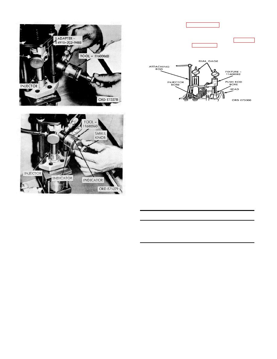
b. Install injector timing fixture (12, fig. B-28) in
injector bore as shown in figure 3-71. Indi- cator extension
must rest in socket of injector push rod. Tighten tool in place
with injector mounting capscrews.
Figure 3-71. Injector push rod timing.
Figure 3-69. Orifice hole burnishing tool installation
c. Rotate engine counterclockwise to top center
firing position. At point of maximum piston rise, set dial
indicator above piston to zero.
d. Rotate engine to 60 degrees ATDC; at this point,
60 degree mark on the moving plunger should be in line with
groove on retainer.
e. Set dial indicator for push rod travel to
zero.
f. Rotate engine in clockwise direction to ap-
proximately 60 degrees BTC of retainer. This is the same
index mark indicated in d, above.
g. Rotate engine in counterclockwise direction until
dial indicator reading shows piston has traveled to location
indicated at first check point under "Piston Travel" in chart 3-
1 below. Read push rod travel on dial indicator and check
read- ing against limits.
Figure 3-70. Orifice plug burnishing
Chart 3 -1. Injection Timing
c. Lubricate O-Rings with GAA lubricant.
Crank angle
Piston travel
Push tube travel
d. Start injectors into bores with inlet toward
degrees
inches
normal
fast
slow
camshaft. Guide them by hand until injectors are
alined in bores and not binding in any manner.
22.5 BTC
0.2032
0.0610
0.0575
0.0645
e. A hard push on injector bodies with butt
15.5 BTC
0.0816
0.0330
0.0307
0.0357
end of a hammer handle will seat injectors. A snap
6.0 ETC
0.0143
0.0135
0.0115
0.0155
should be heard and felt as cups seat in copper
sleeves.
h. Check push rod travel against piston travel
f. Install hold-down clamps, flatwashers, and
capscrews. Tighten capscrews, 30 to 35 foot-
pounds torque.
3-79. Injector Timing
NOTE
Woodruff key used to key camshaft gear to
the camshaft provides one degree advanced
timing and may be identified by a yellow-tip
which is placed in a for-
3-33
|
|
Privacy Statement - Press Release - Copyright Information. - Contact Us |
