 |
|||
|
|
|||
|
Page Title:
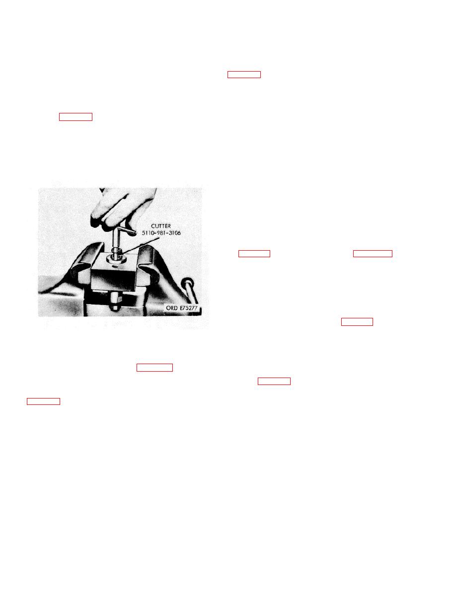
Figure 3-68. Ball seat resurfacing |
|
||
| ||||||||||
|
|
 (3) Remove seating tool and install retainer
*TM 9-2815-213-34
with new gasket. Tighten retainer to 30-40 i
pounds torque.
(4) Recheck injector for ball valve leakage (e
(4) Lock cap on injector and injector adapter (23,
above).
(5) If ball has not seated satisfactorily, it will
(5) Install spring and plunger in injector.
be
necessary to resurface ball seat using seating
surface
NOTE
cutter (6, fig. B-28). Great care must be exercised
Turn injector plunger so class size marking
in
on top of spring retainer is midway
removing only enough material to reface a new seat-
between inlet and drain ports of injector.
ing surface and remove all metal cuttings.
(6) Re-install ball, new gasket, and retaining
(6) Assembly retainer plate over injector and in-
plug
jector adapter.
fl2) and fA3), above.
(7) Perform ball seating check (e above).
NOTE
The side of the retainer plate with two
small pins locates against the injector
adapter as it is installed in the test stand.
All tests on the test stand are performed
without a screen on the injector.
(7) PT injector delivery is adjusted during test by
burnishing inlet orifice plug with orifice hole bur- nishing tool
(9, fig. B-28). Install tool as shown in figure 3-69.
(8) Retract burnishing tool needle by pulling out small
knob. With the needle retracted, tool may be
left in connector during all test operations.
(9) Run injector through a test cycle (d above), check
cc delivery. If delivery is lower than
specifications, turn knob with indicator point until it
1A
is spaced inch from large knob (fig. 3-70).
Figure 3-68. Ball seat resurfacing
(10) Slowly push small knob in until you feel nee- dle
enters orifice plug inside diameter, then turn knob
g. Calibrating PT (Type C) Injectors.
counterclockwise to lock needle shaft to larger knob with
(1) Remove injectors spring and plunk
indicator. Turn indicator knob in until you feel needle contact
Lubricate injector adapter (23, fig. B-28) with h
plug. Index indicator with mark for each two cc increased
pressure lubricant so injector O-Rings will slide i
delivery (fig. 3-70).
adapter without damage to O-Rings.
(2) Install cap and rotate into its notched
(11) Back off adjusting screw and retract needle.
Retest injector (para. d, above). If delivery is more than 116-
117 cc. a new injector body must be install- |
NOTE
ed.
The cap of the adapter contains a movable
dowel screw so the fuel inlet can easily be
(12) Recheck injector delivery for specified 116-|
centered in the sleeve hole after installing the
117 cc with new injector body.
cap.
3-78. Installation
(3) Seat injector in adapter so injector inlet
a. Inspect injector, it must be clean and the screen
alines
around inlet groove must have no gaps or holes.
with adapater inlet after injector body is rotated into
b. Check that copper sleeves in cylinder heads are
adapter. Cap pin must seat in slot in adapter.
clean, free of chips, and carbon particles.
Check to be sure injector inlet is centered in sleeve
inlet hole.
3-32
|
|
Privacy Statement - Press Release - Copyright Information. - Contact Us |
