 |
|||
|
|
|||
|
Page Title:
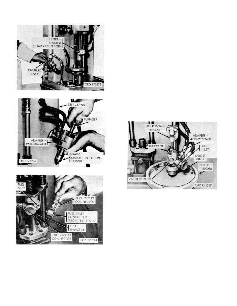
Figure 3-62. Air pressure adjustment. |
|
||
| ||||||||||
|
|
 *TM 9-2815-213-34
test stand or other pressure source to injector inlet or
adapter.
(12) Start test stand or other source of fuel and set
pressure at 50 psi.
(13) Shift target ring in base of tool so one spray
stream hits center of No. 1 or index window. This is tallest
window and is next to target
slide handle.
(14) Each spray stream must hit a window in the
target.
(15) If a stream hits above, below, left, or right of a
small window, shift the target ring so No. 1 window is at that
stream. If stream is still outside No. 1 window, cup is
defective or spray hole is dirty. Clean spray holes with
compressed air and recheck cup. If spray pattern is still de-
Figure 3-62. Air pressure adjustment.
fective, discard cup or check to make sure proper target ring
is being used.
NOTE
For a cup to be acceptable or more than one stream
must require the increased tolerance of the No. 1
window.
Figure 3-63. Master injector installation.
Figure 3-65. Injector mounted in test stand
(16) After testing, assemble plunger with spring in
body and store in clean place until ready for flow test.
d. Injector Flow Check.
(1) The injector test stand must be located near hot
and cold water connections. Water tem- perature, controlled
by a mixing valve, is used to maintain test fuel at an 80/100
degree Fahren- heit temperature range.
(2) Fill test fuel tank a/4 full of test fuel and maintain
this level or higher during test. Test fuel capacity is
approximately five gallons.
(3) Fill hydraulic fluid reservoir to half
Figure 3-64. Fuel inlet installation
(10) Tighten knurled knob to seal plunger
bore.
(11) Attach fuel inlet line from injector
3-30
|
|
Privacy Statement - Press Release - Copyright Information. - Contact Us |