 |
|||
|
|
|||
|
|
|||
| ||||||||||
|
|
 *TM 9-2815-213-34
level in sight bulb with clean type A auto transmission
fluid. Be careful not to allow oil to standpipe in center
of reservoir, figure 3-59.
(4) Fill cam box with 3 inches of OE
lubricating oil. Refill with oil level drops to glass.
(5) Plug electrical connection into recel
carrying necessary voltage to operate test stand
(6) Before clamping on injector in test stand
must be timed by rotating timing wheel so
mark and pointer are alined as shown in figure
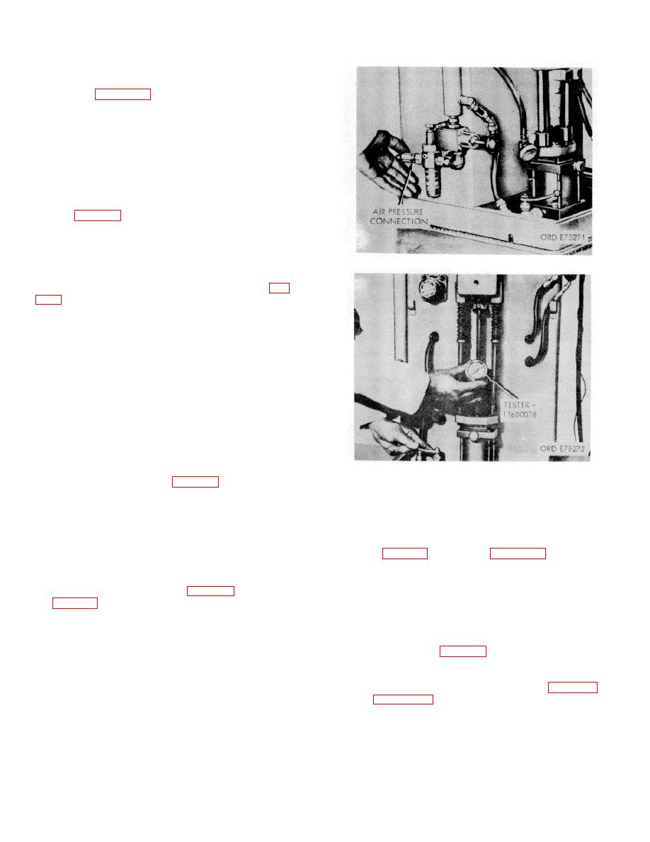
(7) Shop air pressure regulated by al
regulator is used to apply balanced force on hydl
system, (fig. 3-66). Air gage at top of hydraulic I voir
is used as a reference indicating that pre has not
changed after being set using a load tei during test
stand calibration.
Figure 3-66. Test stand air pressure connection.
(8) When air valve is opened, air travels ul in
center of tube type hydraulic reservoir and 4
downward pressure against column of hydraulic (fig.
(9) When both air valve and hydraulic valve3-
61) are opened, hydraulic fluid is admitted piston in
cylinder and lifts injector into clamped tion. Any leak
in hydraulic clamping system directly affect injector
loading and must not be per-mitted.
(10) In clamped position and with appropriate
link in place, tension on injector is same as it
operating engine. Use of improper link will clamp
load and upset delivery valves.
(11) Fuel is delivered to injector through
connector. Fuel pressure here is controlled a point
by connecting line and pressure reg (3-64).
(12) The second connection with clear plastic
Figure 3-67. Load cell tester.
line
is injector outlet connection (fig. 3-64) which c drain
3-63), assembly may be hand held. Do not place in
fuel from injector back to tank.
test stand holding device.
(13) During test stand operation, operator a
(3) Turn on test stand, and adjust pressure to 150
test cycle which diverts fuel to vial graduate so
psi.
amount of fuel being injected can be measure
(4) Check orifice plug inlet opening of injector
(14) Fuel is delivered to vial during a mea
adapter (23, fig. B-28)ras shown in figure 3-62, for
number of strokes as recorded by counter (fig. 3
leakage past ball valve.
e. Ball Valve Seating Check.
(1) Attach test stand inlet pressure line to
NOTE
connection injector adapter (23, fig. B-28) as s
Insure plunger is seated in cup.
in (fig. 3-64).
(5) If leakage is observed, the ball must be
(2) Hold injector plunger down against its
reseated.
seat in
injector cup with injector in vertical position (fig.
(1) Remove retainer plug at top of injector body.
Leave ball in place, but discard retainer gasket.
(2) Screw check ball seating tool (5, fig. B-28) as
shown in figure 3-54, down against ball and tighten to 50
inch-pounds torque.
3-31
|
|
Privacy Statement - Press Release - Copyright Information. - Contact Us |