 |
|||
|
|
|||
|
Page Title:
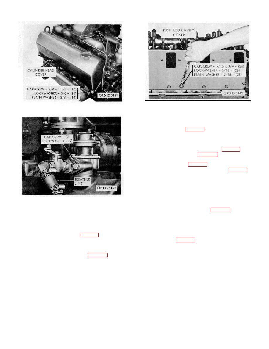
Figure 2-12. Cylinder head covers-removal/installation. |
|
||
| ||||||||||
|
|
 *TM 9-2815-213-34
Figure 2-14. Push rod cavity covers-
Figure 2-12. Cylinder head covers-removal/installation.
removal/installation.
(5) Remove 24 push rods (16 valve and 8 injector)
from tappets.
(1) Remove eight capscrews and flat washers and
nylon inserts securing injector clamps to cylinder head.
(2) Remove clamps.
(3) Pull injectors from cylinder head (fig. 2-17).
crossheads by lifting each straight up from guides.
(1) Attach cylinder head lifting plate (45, fig. B-28).
(2) Attach lifting hook of chain fall, or other suitable
lifting device, to lifting plate. Take-up slack in chain or
cable.
(3) Remove 16 capscrews and flat washers (fig. 2-
18) securing heads to block (eight cap screws per head).
Figure 2-13. Crankcase breather tube-
(4) Using lifting device remove each cylinder head.
removal/installation.
Remove gaskets.
(1) Remove 16 capscrews and lockwashers (eight
(c) Remove ten capscrews, lockwashers, and flat
per cylinder head) securing eight tappet guide plates to
washers securing cover to cylinder head.
heads (four per head).
(d) Remove cover, breather and pressurizing unit,
(2) Remove guide plates.
and gasket.
(3) Lift tappet assembly from block.
(1) Remove 26 capscrews, lockwashers, and flat
(1) Cut lockwire on six capscrews securing flywheel
washers securing each cover to cylinder heads.
to crankshaft adapter.
(2) Remove covers and gaskets.
(2) Remove two opposing capscrews.
(3) Insert two 5/8 x 6-inch headless studs in
(1) Loosen all push rod adjusting screw locknuts
and back-off adjusting screws.
(2) Secure rocker arms with rubber bands.
(3) Remove ten capscrews and flat washers
securing each irocker arm to respective cylinder head.
(4) Remove rocker arms and brackets.
2-9
|
|
Privacy Statement - Press Release - Copyright Information. - Contact Us |