 |
|||
|
|
|||
|
Page Title:
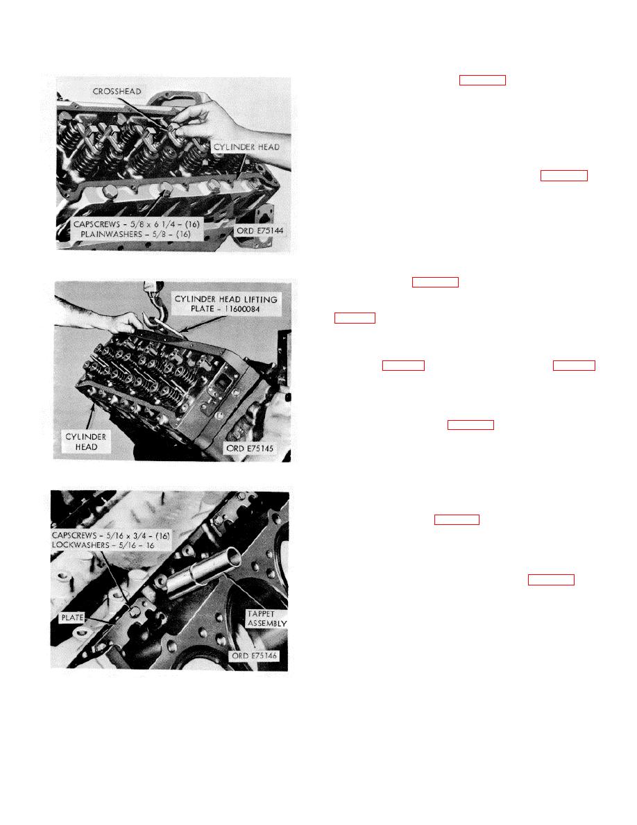
Figure 2-18. Valve crossheads - removal/installation. |
|
||
| ||||||||||
|
|
 *TM 9-2815-213-34
(3) Remove adapter.
(1) Remove eight cap screws, lockwashers,
and flat washers securing oil pan to flywheel housing.
(2) Remove
seven
cap
screws
and
lockwashers securing flywheel housing to engine block.
(3) Using a rubber mallet, or brass head
driver, free housing from block and remove housing and
gasket.
(1) Straighten lockplate fingers on two cap
screws securing camshaft thrust plate to engine block.
(2) Remove
cap
screws
and
discard
lockplates.
(3) Remove camshaft and gear from block.
Rotate camshaft gear slightly while pulling.
(4) Remove spacer plate and two plate to block
Figure 2-18. Valve crossheads - removal/installation.
gaskets.
(1) Remove six cap screws and lockwashers,
on right side of pan, securing pan inspection plate (6,
(2) Remove inspection plate and gasket.
(3) Reach inside oil pan and remove two cap
screws and lockplates securing the oil pump by-pass
tube (13, fig. B-9) and oil suction tube (20, fig. B-9),
respectively, to the oil pan.
(4) Remove 12 cap screws, lockwashers, and
flat washers securing oil pan to block.
(5) Remove pan and gasket.
(1) Remove cap screw, nut, lockplate, and
clamps securing oil suction tube to block.
(2) Remove cap screw and lockplate securing
Figure 2-19. Cylinder heads - removal/installation.
oil by-pass tube to block.
(3) Remove four cap screws and lockplates
securing oil pump to block.
(4) Remove pump and tubes from block.
(1) Remove 12 cap screws and lockwashers
securing cover to engine block.
(2) Remove cover and gasket. Pull straight out
to avoid damaging the dowels.
NOTE
The following instructions cover the
removal of one connecting rod and
piston assembly from engine block.
Remove remaining seven rods and
pistons in the same manner.
Figure 2-20. Valve and injector tappets -
removal/installation.
(2) Cut and remove lockwire on adapter to
crankshaft securing screws and remove cap screws.
2-11
|
|
Privacy Statement - Press Release - Copyright Information. - Contact Us |