 |
|||
|
|
|||
|
Page Title:
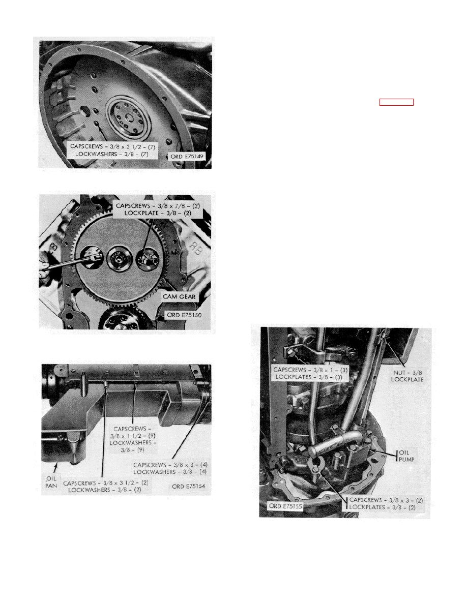
Figure 2-23. Flywheel housing - removal/installation. |
|
||
| ||||||||||
|
|
 *TM 9-2815-213-34
(5)
Tape bearing half shell to cap as re.
moved.
(6) Using a wooden stick, or hammer handle.
push piston up out cf cylinder.
(7) Tape upper bearing half shell to rod.
(8) Assemble cap on rod and tag to identify
assembly with cylinder.
(1) Remove 19 main bearing side locking bolts
and plain washers.
(2) Remove 10 main bearing cap screws and,
plain washers securing caps to block.
(3) Using a small pry bar, loosen and remove
the bearing cap and bearing half shell. Mark half shells
to identify with mating cap.
(4) Remove rear bearing thrust half rings.
Figure 2-23. Flywheel housing - removal/installation.
CAUTION
Insure that lifter hooks are rubber
covered or otherwise prepared to
prevent metal-to-metal contact with shaft
throws.
(5) Using an overhead chain fall, or other
suitable lifting device, attach a double hook lifter to two
shaft throws and remove crankshaft from block.
(6) Remove upper bearing half shells and tag
on removal with mating bearing cap identification.
(7) Remove rear bearing upper thrust halfrings.
Figure 2-24. Camshaft, gear and spacer plate-
removal/installation.
Figure 2-25. Oil pan-removal/installation.
Figure 2-26. Oil pump assembly-removal/installation.
and remove cap and
bearing half from crank
shaft.
2-13
|
|
Privacy Statement - Press Release - Copyright Information. - Contact Us |