 |
|||
|
|
|||
|
Page Title:
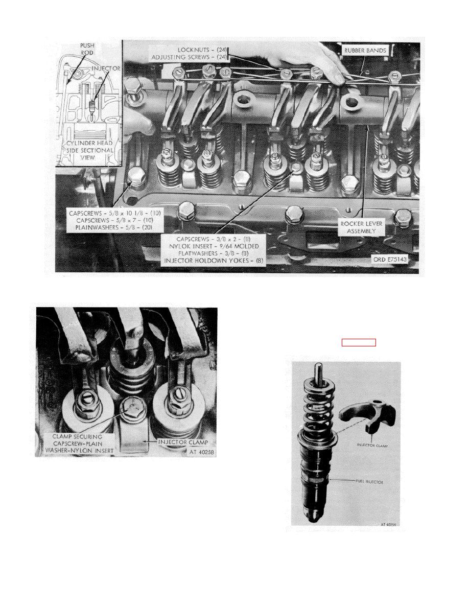
Figure 2-15. Rocker arms and push rods--removal/installation. |
|
||
| ||||||||||
|
|
 *TM 9-2815-213-34
Figure 2-15. Rocker arms and push rods--removal/installation.
screws to pull flywheel from adapter onto the six-inch
studs.
(7) Remove the flywheel by sliding over studs.
Remove studs.
(1) Remove grease retainer cup from adapter base.
Figure 2-16. Injector clamps--removal/installation.
the holes and secure into the adapter. These shall serve
as a support for removal of the flywheel.
(4) Remove two of the slotted head screws and
install 1/2-13 x 2 1/2, inch capscrews.
(5) Remove the four remaining flywheel to adapter
securing capscrews.
(6) Alternately turn-in the 1/2-inch cap
Figure 2-17. Fuel Injector and hold-down clamp.
2-10
|
|
Privacy Statement - Press Release - Copyright Information. - Contact Us |