 |
|||
|
|
|||
|
|
|||
| ||||||||||
|
|
 *TM 9-2815-213-34
drive gear from camshaft gear, and remove compressor.
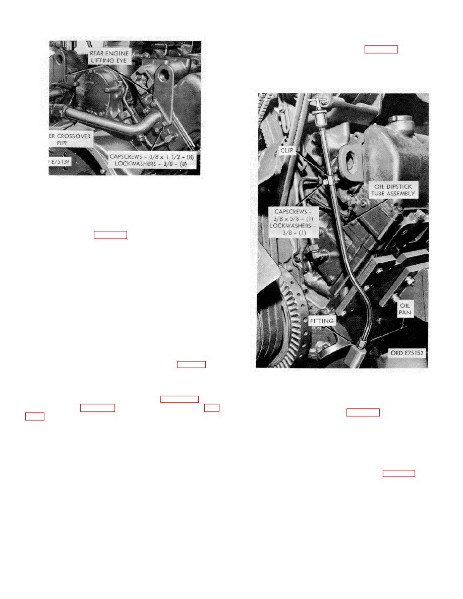
(1) Remove capscrew and lockwasher securing
tube clip to engine block.
(2) Disconnect tube at oil pan fitting and remove
tube.
Figure 2-10. Water crossover pipe and engine lifting
eyes--removal/installation.
rear end of each cylinder head and remove cross-over
with flexible metallic drain return line at tached.
(6) Loosen two capscrews, securing fuel pump
support bracket (32, fig. B-18), to engine block.
(7) Remove four capscrews, lockwashers, and flat
washers, securing fuel pump to air compressor housing
and support bracket.
(8) Slide support bracket towards front, pull pump
towards front and remove from compressor. Remove
gasket.
(9) Remove two capscrews, lockwashers, and flat
washers securing bracket to block and remove bracket.
NOTE
The fuel pump is driven through a
freefloating coupling between the pump
and compressor. Insure that coupling
and plate are removed with pump.
(1) Disconnect coolant input and output lines at
Figure 2-11. Oil dipstick tube assembly-
compressor.
removal/installation.
(2) Disconnect air discharge line at compressor.
(3) Remove six capscrews (10, fig. B-25) and
2-11. Internal Components
lockwashers (9, fig. B-25) securing rear support (8, fig.
(1) Right Head Cover.
(4) Remove support and gasket.
(a) Remove ten capscrews, lockwashers, and plain
(5) Pull compressor and drive assembly toward front
washers securing cover to head.
of engine, to disengage compressor
(b) Remove cover and gasket.
(2) Left Head Cover.
(a) Loosen hose clamp securing breather tube to
crankcase breather and pressurizing unit (fig. 2-13).
(b) Remove breather tube from unit.
2-8
|
|
Privacy Statement - Press Release - Copyright Information. - Contact Us |