 |
|||
|
|
|||
|
Page Title:
INSTALLATION OF INTAKE AND EXHAUST MANIFOLDS AND OIL LEVEL GAGE SUPPORT CLAMP BRACKET |
|
||
| ||||||||||
|
|
 b. Install Intake and Exhaust Manifolds and
a. Preparation for Valve Clearance Adjust-
Oil Level Gage Support Clamp Brackets. Refer
ment.
to figures 266 and 267 and reverse the sequence
of illustrations and instructions to install the
(1) Rotate the crankshaft clockwise, as
viewed from the fan end, until the No.
support brackets.
2 intake valve is in the wide open posi-
tion. This can be determined when the
Note. Intake and exhaust manifolds must be
valve rocker pad is holding the valve
installed simultaneously.
down as far as it will go, and its push
rod is as high as it will go. When the
No. 2 intake valve is in the wide open
position, the No. 2 exhaust valve, and
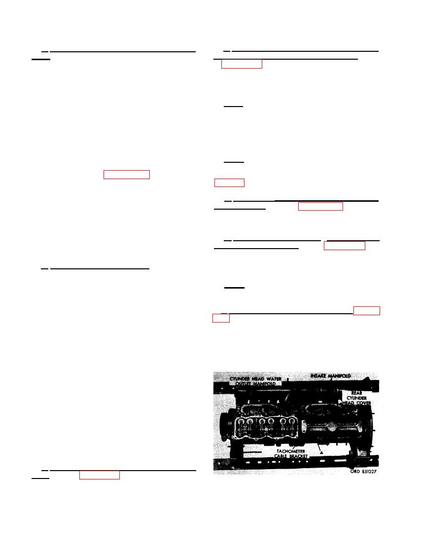
WATER OUTLET MANIFOLDS AND
No. 1 intake valve are completely closed
REAR CYLINDER HEAD COVER
and in position to be adjusted.
Note. The front cylinder head cover will not
(2) Set No. 1 intake and No. 2 exhaust valve
be installed until after the fuel injection pump
clearance. Figure 486. (A) Loosen
has been installed and timed to the engine
adjusting screw nut and screw as neces-
sary. (B) Place a 0.015-inch feeler gage
a. Position Cy linder Head Water Outlet Man-
between No. 1 intake valve rocker arm
and the valve stem. Tighten the adjust-
ifold Gaskets. Refer to figure 266 step A and
position the six cylinder head water outlet mani-
ing screw until the feeler gage can be
withdrawn with a slight drag. Tighten
fold gaskets.
the adjusting screw nut to secure the
b. Install Front and Rear Cylinder Head
setting. (C) Set No. 2 exhaust valve
Water Outlet Manifolds. Refer to figure 26 5 and
clearance to 0.025-inch in the same
reverse the seauence of instructions to install
manner.
the front and rear cylinder head water outlet
b. Valve Adjusting Sequence. Turn crank-
manifolds.
shaft clockwise. as viewed from the fan end.
approximately 120 degrees until No. 4 intake
Note. Install new rear cylinder head cover
valve is fully open, With No. 4 intake valve
gasket rear cylinder head.
fully open, adjust No. 4 exhaust valve and No. 5
intake valve. Following the sequence of turning
c. Install Rear Cylinder Head Cover. Figure
the crankshaft clockwise approximately 120 de-
grees each time, set remaining valves as fol-
gasket. (B) Secure rear cylinder head cover and
lows.
tachometer cable bracket to cylinder head using
(1) With No. 1 intake valve fully open, adjust
seven 5/16- inch lock washers and 5/16 x 7/8
No. 1 exhaust and No. 3 intake valves.
cap screws. (C) Install one 5/16- inch plain
washer and 5/16-inch self- locking nut.
(2) With No. 5 intake valve fully open, adjust
No. 5 exhaust and Np. 6 intake valves.
(3) With No. 3 intake valve fully open, adjust
No. 3 exhaust and No. 2 intake valves.
(4) With No. 6 intake valve fully open, adjust
No. 6 exhaust and No. 4 intake valves.
270. INSTALLATION
F INTAKE AND EX-
HAUST MANIFOLDS AND OIL LEVEL
GAGE SUPPORT CLAMP BRACKET
a. Install Intake and Exhaust Manifold Gas-
kets. Refer to figure 268, step A and install new
intake and exhaust manifold gaskets on intake
and exhaust port studs.
HEAD COVER.
310
|
|
Privacy Statement - Press Release - Copyright Information. - Contact Us |