 |
|||
|
|
|||
|
Page Title:
INSTALLATION OF OIL FILTERS AND FUEL INJECTION PUMP OIL SUPPLY HOSE |
|
||
| ||||||||||
|
|
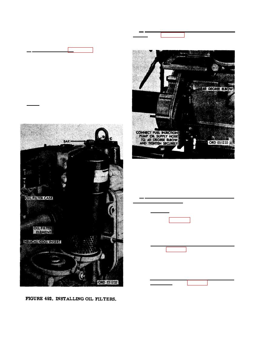
 b. Install Fuel Injection Pump Oil Supply
Hose. Refer to figure 493 and install fuel in-
FUEL INJECTION PUMP OIL SUPPLY
jection pump oil supply hose.
HOSE
a. Install Oil Filters. Figure 492. (A) Posi-
tion rear oil filter case gasket in the recess
provided in oil cooler and oil filter housing.
(B) Position rear oil filter element on housing.
(C) Position rear oil filter case over element
and start bar threads into helical coil threaded
insert in oil cooler and oil filter housing.
(D) Secure rear oil filter case by tightening
bar to a torque of 60 pound feet. Case must be
properly seated against case gasket.
Note. The front oil filter element and case
are installed in the same manner.
PUMP OIL SUPPLY HOSE.
PUMP ASSEMBLY
a. Preparation of Fuel Injection Pump As-
sembly for Installation.
(1) General. A new or rebuilt fuel injection
pump is supplied for installation as
shown in figure 76, The injection pump is
prepared for installation following the
procedures outlined in (2) through (5)
below.
(2) Remove injection pump timing covers.
Refer to figure 76 and reverse the se-
quence of instructions to remove timing
cover, timing window cover, dirt plugs
or caps, and automatic advance unit
shaft lock washer and nut.
(3) Install fuel tube and hose elbows and
connector. Refer to figures 74 and 75, and
reverse the sequence of instructions to
install tube and hose elbows and con-
nector.
314
|
|
Privacy Statement - Press Release - Copyright Information. - Contact Us |