 |
|||
|
|
|||
|
Page Title:
Overhaul of Fuel Injection Drive Couplers |
|
||
| ||||||||||
|
|
 Table 6-46. Fuel Injection Pump Drive Couplers, Fuel Injector Nozzles,
Piston Oiler Nozzles and Time Totalizing Meter
Disassembly
Cleaning
Component
Repair
Assembly
Fuel Injection
Pump Drive
Splined Coupler
Diaphragm
Coupler
Fuel Injector
Para 4-26,
Nozzles
4-27, Figs.
4-169, 4-168
4-167
Piston Oiler
Nozzle
Time Total-
izing Meter
6-256
Overhaul
of
Fuel
Injection
Drive
a. Disassembly. Disassemble the drive splined
coupler following instructions which accompany
Disassemble
drive
diaphragm
coupler
following
instructions
which
accompany
Disassemble
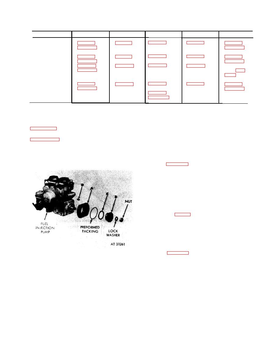
1. Refer to figure 4-59 and 4-61 to remove front coupler
sleeve and hub from injection pump.
2. Separate front coupler sleeve (A) and injection pump
hub (B).
3. Remove quad ring (C) from coupler sleeve.
4. Remove Woodruff key (D) from pump shaft.
Note. Keep front coupler sleeve and hub
together. Place them with the rear coupler sleeve
and drive shaft hub on rear fan drive housing.
Check identification marks made during engine
disassembly (fig. 4-52) to make sure these parts
match. These parts are mated and must be kept
together.
Assemble
1. Position Woodruff key (D) in pump shaft.
2. position quad ring (C) in internal groove of front
coupler sleeve (A).
3. Install injection pump hub (b) in coupler sleeve.
4. Refer to figure 4-63 to install hub and sleeve on pump
shaft and install preformed packing.
Disassembling
or
assembling
fuel
injection
pump
drive
splined
coupler.
6-215
|
|
Privacy Statement - Press Release - Copyright Information. - Contact Us |