 |
|||
|
|
|||
|
Page Title:
Figure 4-52. Removing fuel injection pump splined coupler bolts. |
|
||
| ||||||||||
|
|
 Note. The fuel injection pump splined coupler
sleeves and hubs must be identified with
identical marks to prevent mismating of parts.
T h e sleeves and hubs are matched for each
assembly and must not be interchanged between
assemblies.
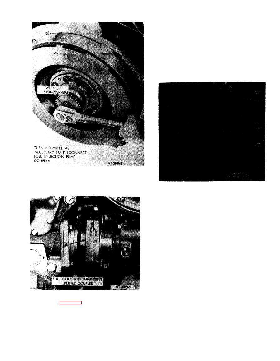
Figure 4-52. Removing fuel injection pump
splined coupler bolts.
Figure 4-51. Positioning fuel injection pump
coupler by turning flywheel using splined
wrench -5l2O-793-7895.
1.
Separate coupler sleeves (.4).
2. Remove and discard preformed packing (B) from fuel
injection pump coupler sleeve.
Figure 4-53. Separating fuel injection pump
coupler sleeves.
1. Torn engine using splined wrench -5120-793-7895 as
shown in figure 4-51, until fuel injection pump coupler
bolts are accessible.
2. Stamp identification marks (B) on both injection
coupler sleeves.
3. Remove four bolts (C), lock washers, and lock plates.
4-27
|
|
Privacy Statement - Press Release - Copyright Information. - Contact Us |