 |
|||
|
|
|||
|
Page Title:
Section V. OVERHAUL (REBUILD) OF HIGH-RANGE CLUTCH ASSEMBLY AND CONVERTER TURBINE SHAFT |
|
||
| ||||||||||
|
|
 Section V. OVERHAUL (REBUILD) OF HIGH-RANGE CLUTCH
ASSEMBLY AND CONVERTER TURBINE SHAFT
repair recommendations. Also make certain that oil
5-17. Description
passages and orifice plug (10) are open and clean in
Refer to paragraph 2-2 for high-range clutch
converter turbine shaft (9). Inspect piston (27) to
description and to paragraph 2-10 for converter
make certain that the two balls in clutch piston are
turbine shaft description.
free and that staking is satisfactory. Repair and
5-18. Disassembly
overhaul (rebuild) points of measurement for fits,
clearances, and wear limits are indicated by small
NOTE
letters in figure 5-62. Refer to paragraph 6-3 and
All related items not covered in a and b
below were removed from the transmission
5-21. Assembly
as outlined in paragraph 5-6, steps 33
through 35 (fig. 5-33 through 5-35). No
NOTE
further disassembly of those parts is
All items not covered in a and b below are
required.
installed as outlined in paragraph 5-58,
step 24 (fig. 5-106). No overhaul (rebuild)
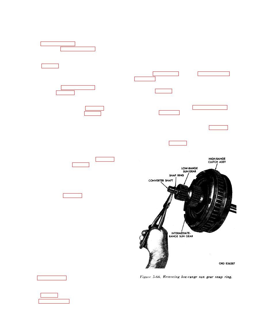
(1) Remove snap ring (fig. 5-66) from con-
of such components is required or
verter shaft.
recommended.
(2) Remove low-range sun gear and in-
termediate-range sun gear from converter shaft.
(1) If bushing (23) was removed, install new
(3) Remove converter shaft from high-range
bushing using replacer 5120-572-8658 and handle
clutch assembly.
5120-316-9182 (fig. 5-69).
(4) Remove retainer snap ring (12) and two
hook-type seal rings (11) from converter turbine
shaft assembly (8).
(1) Remove snap ring (fig. 5-67) from high-
range clutch housing assembly.
(2) Remove reaction plate and four internal-
splined and three external-tanged clutch plates.
(3) Using sleeve, part of kit 5180-572-8607,
and a press, remove snap ring from high-range
clutch housing hub (fig. 5-68).
(4) Remove return spring retainer (30) and
springs (28 and 29) from housing (22).
(5) Remove high-range clutch piston assembly
(2) from housing by tapping housing with a soft
hammer.
(6) Remove Teflon seal ring (25) and seal ring
expander (26) from piston (27)
(7) Remove hook-type seal ring (24) from
housing.
(8) Remove bushing (23) from housing only if
replacement is necessary.
WARNING
Do not dispose of Teflon seals by burning;
toxic gases are produced.
5-19. Cleaning
Refer to paragraph 5-2 for cleaning recom-
mendations.
Refer to paragraph 5-3 for general inspection and
|
|
Privacy Statement - Press Release - Copyright Information. - Contact Us |