 |
|||
|
|
|||
|
Page Title:
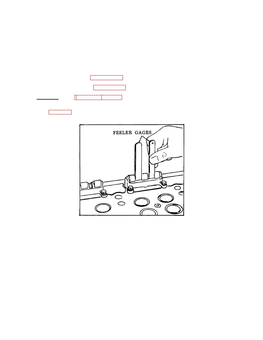
Figure 3-83. Checking Cam Follower to Guide Clearance. |
|
||
| ||||||||||
|
|
 TM 55-1930-208-24
(2)
Assemble three lower spring seats (4), three springs (3), three upper spring seats (2), and locknut on
three push rods (5). Slide the three push rod assemblies in position from the bottom of the head. Install
three spring retainers (1).
(3)
Note the oil hole in the bottom of the cam follower. With the oil hole directed away from the exhaust
valves, slide the cam follower (9) in position from the bottom of the head.
(4)
Install cam follower guide (8) and secure with two lockwashers (7) and two screws (6). Torque screws to
12-15 lb-ft (16-20 Nm).
(5)
Install rocker arms per paragraph 3-36.
(6)
Install cylinder head per paragraph 3-38.
f.
Adjustment. (Refer to figures 3-83 and 3-84).
(1)
Check that there is at least .005 inch clearance between the cam follower legs and cam follower guide
Figure 3-83. Checking Cam Follower to Guide Clearance.
3-141
|
|
Privacy Statement - Press Release - Copyright Information. - Contact Us |