 |
|||
|
|
|||
|
|
|||
| ||||||||||
|
|
 TM 55-1930-208-24
3-39. VALVE OPERATING MECHANISM - Continued.
f.
Adjustment - Continued.
(2)
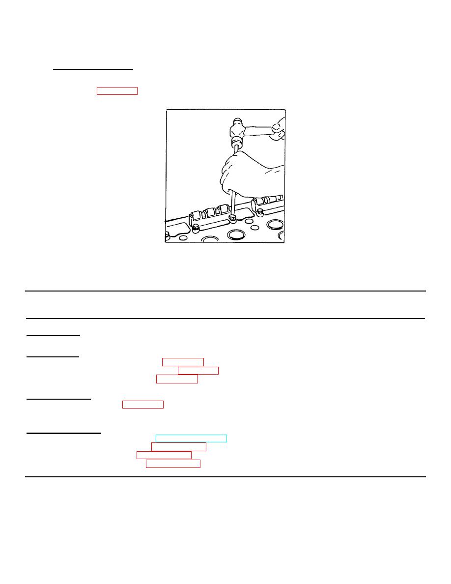
If there is insufficient clearance, loosen guide bolts slightly and tap each corner of the guide with a brass
rod (figure 3-84). Then, retighten bolts to specified torque 12-15 lb-ft (16-20 Nm).
Figure 3-84. Adjusting Cam Follower Guide.
3-40. VALVES, INTAKE AND EXHAUST.
This task covers:
a. Removal
b. Cleaning
c. Inspection
d. Repair
e. Installation
INITIAL SETUP:
Tools Required:
Tool Kit, General Mechanic's (Item 1, Appendix B)
Remover, Spring, P/N J3092-01 (Item 44, Appendix B)
Valve Spring Compressor (Item 46, Appendix B)
Materials Required:
Oil, Lubricating (Item 12, Appendix C)
Wood Block (2" X 3" X 30")
Equipment Conditions:
Engine shut down (paragraph 2-11, TM 55-1930-208-10).
Fuel pipes and injectors removed (paragraph 3-35).
Rocker arms shafts removed (paragraph 3-36).
Exhaust valve bridges removed (paragraph 3-39).
3-142
|
|
Privacy Statement - Press Release - Copyright Information. - Contact Us |