 |
|||
|
|
|||
|
Page Title:
Section V. TESTS AND ADJUSTMENTS |
|
||
| ||||||||||
|
|
 c. Refer to figure 18 for instructions
covering installation of the positork
a. Refer to figures 17 through 13 for
drive assembly on the armature.
instructions covering assembly of the pin-
ion housing.
Note.
Before installing the lever
and shaft assembly, lubricate the shaft
with grease, Specification MIL-G-3278.
b. Refer to figures 12 and 11
for
instructions covering installation of the
pinion housing and brushes.
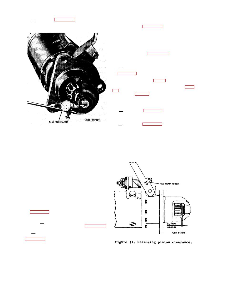
c. Measure the end play of the arma-
ture shaft using a dial indicator as shown
in figure 40. If the end play is not be-
tween 0.005 to O.O3O-inch install or re-
move fiber washers (A, fig. 13) as neces-
sary. This can be accomplished by pulling
the brushes out of their holders (fig.
assembly (fig. 21).
Replace the above
parts and recheck end play.
a. Refer to figures 8 through 5 for
instructions covering assembly of the
switch assembly.
b. Refer to figure 4 for instruction
covering installation of switch assembly
and the end cover.
Measuring armature end play.
Section V.
TESTS AND ADJUSTMENTS
35. General
Whenever a starter is tested, it should
be checked for any unusual noises or vi-
bration that might indicate an unservice-
able condition. If either condition ex-
ists, further testing should not be at-
tempted and starter returned for rebuild.
36. Pinion
Clearance
Check starter to make certain positork
drive is fully engaged when switch ener-
gizes starter motor and pinion clearance
is between 0.010 to 0.050-inch as shown
in figure 41. Perform the pinion clear-
ance check as follows:
a. Loosen locknut and turn adjusting
bolt to the position shown in figure 42.
b. Use screwdriver or wrench to engage
switch by compressing spring as shown in
|
|
Privacy Statement - Press Release - Copyright Information. - Contact Us |