 |
|||
|
|
|||
|
Page Title:
Repair of Timing Device Assembly |
|
||
| ||||||||||
|
|
 TM 9-2910-226-34
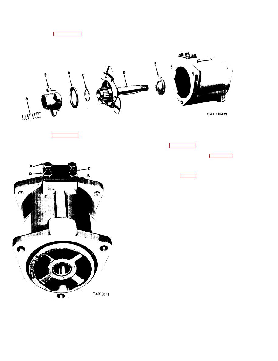
3-27. Repair of Timing Device Assembly. a.
timing device springs (A). Remove sliding gear (B),
Disassembly.
end play spacer (C), sliding gear spacer (D) and
(1) Refer to figure 3-95. Remove the three
spider thrust plate (F).
Figure 3-95. Removing sliding gear, spider assembly and associated parts.
(2) Refer to figure 3-96. Remove four capscrews
b. Inspection and- Repair. Inspect and repair
(A), lockwashers (B), and timing cover (C). Remove
timing device assembly as follows:
and discard timing cover gasket (D).
(1) Refer to figure 3-97. Check the components
of the timing device assembly against the limits
specified in the repair standards (para 3-63) and
replace the components when they do not meet these
requirements.
KEY to fig. 3-97
A Preformed packing
B -inch lockwasher
C 1/4x5/8 machine screw
D Timing cover
E Timing cover gasket
F Thrust plate
G Weight and spider assembly
H Housing assembly
1 Bushing type bearing
2 Housing
J End play spacer
K Sliding gear spacer
L Sliding gear
M Timing device spring
N Camshaft nut
P Timing device
Q Camshaft nut setscrew
Figure 3-96. Removing or installing timing cover.
3-60
|
|
Privacy Statement - Press Release - Copyright Information. - Contact Us |
