 |
|||
|
|
|||
|
Page Title:
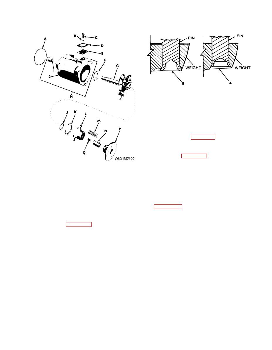
Figure 3-97. Timing device assembly, exploded view. |
|
||
| ||||||||||
|
|
 TM 9-2910-226-34
Figure 3-98. Comparison of timing device weight pins.
(5) Examine the weight on the spider assembly
(G) for freedom of movement. Replace the weight
and spider assembly when the weights do not move
freely.
Assemble the timing device
C . Assembly.
assembly as follows:
(1) The parts for the universal timing device
repair kit are listed in Appendix B. When any part in
the repair kit-- 5702661 except hardware items, must
be replaced, replace all parts applicable to the timing
device assembly.
(2) Refer to figure 3-97. Do not install timing
cover at this time. The timing device assembly parts
will be installed during assembly of pump.
Figure 3-97. Timing device assembly, exploded view.
3-28. Repair of Hydraulic Head Assembly.
(2) Inspect the timing device housing (H) for
cracks, nicks, burs, and damage to mating surfaces.
NOTE
Replace the housing when cracked. Minor nicks or
Except for the upper and lower head
burs may be cleaned up with crocus cloth.
preformed packings, component parts of the
(3) Inspect the splines of the weight and spider
hydraulic heads are not spare parts. If any
assembly (G), sliding gear (L), and timing device
part shows evidence of wear or other damage
hub (P) for damage, wear, and fit on mating sur-
replace the complete head assembly. Refer to
faces. Remove minor burs and scratches from splines
with crocus cloth. Replace all parts having splines
identified by American Bosch part number
which are damaged or do not fit properly with
HD9070A (FSN 2910-084-0259), used on
mating surfaces.
some code F pumps, are prone to cracking
(4) Refer to figure 3-98. Inspect the pins that
between the delivery valve screw and
secure the weights to the spider. Weight and spiders
cylinder No. 3 port. These heads must be
assembled with pin (A) should be discarded and
replaced upon disassembly of injection
replaced. Weight and spiders assembled with pin (B)
pump.
can be reused if the pins have no end play and are
tight.
3-61
|
|
Privacy Statement - Press Release - Copyright Information. - Contact Us |