 |
|||
|
|
|||
|
Page Title:
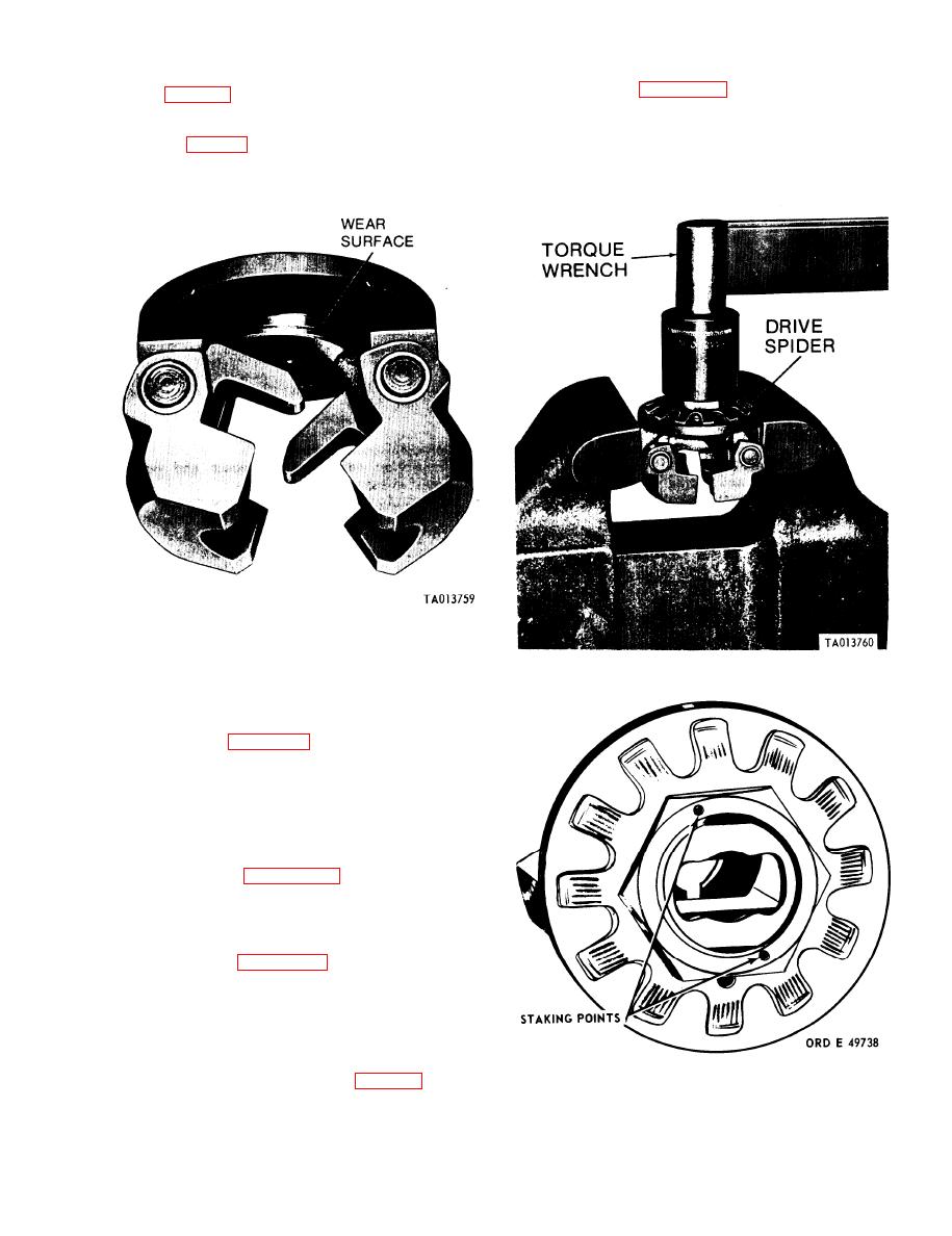
Figure 3-92. Inspecting friction drive spider wear surface. |
|
||
| ||||||||||
|
|
 TM 9-2910-226-34
(4) Refer to figure 3-94. Using a center punch,
and D, fig. 3-91) and the mating surface on the
stake spring disk adjusting nut at two points in-
friction drive spider for evidence of wear or damage.
dicated to prevent nut from loosening.
(2) Carefully inspect the mating surface of the
(5) Remove friction drive spider and governor
drive hub (fig. 3-92) and spider for evidence of wear
assembly from vise.
or damage.
Figure 3-92. Inspecting friction drive spider wear surface.
(3) If damage or wear is evident on any part,
replace the complete assembly. Retain the weight
Figure 3-93. Checking friction drive spider slippage.
and spider assembly for possible repair.
c. Assembly. Assemble the governor weight and
spider assembly as follows:
(1) Refer to figure 3-91. Install retainer (if used),
0.035-inch spring disk spacer (E), inner spring disk
(D), 0.035-inch spring disk spacer (C), outer spring
disk (B) and nut (A).
NOTE
The outer spring disk contains an iden-
tification hole to distinguish it from the inner
disk.
(2) Refer to figure 3-90. Position governor
weight assembly in vise using 3/8 x 3/4-inch steel
bar stock as shown. Tighten hub nut to 80-85
foot-pounds. Remove friction drive spider and
governor weight assembly and bar stock from vise.
(3) Refer to figure 3-93. Install friction drive
spider and governor weight assembly in vise
equipped with soft metal jaws as shown. Lubricate
the spring disk bearing surface with engine oil and
take a running torque reading. Torque reading
should be between 48 and 72 inch-pounds. If the
torque reading falls below these limits, install a
thinner spring disk spacer (E, fig. 3-91). If the
Figure 3-94. Staking spring disk adjusting nut.
torque reading exceeds these limits, replace the
governor weight and spider assembly.
3-59
|
|
Privacy Statement - Press Release - Copyright Information. - Contact Us |
