 |
|||
|
|
|||
|
Page Title:
Repair of Governor Weight and Spider Assembly |
|
||
| ||||||||||
|
|
 TM 9-2910-226-34
NOTE
Sub-paragraph (21) below applies to code A
pumps only.
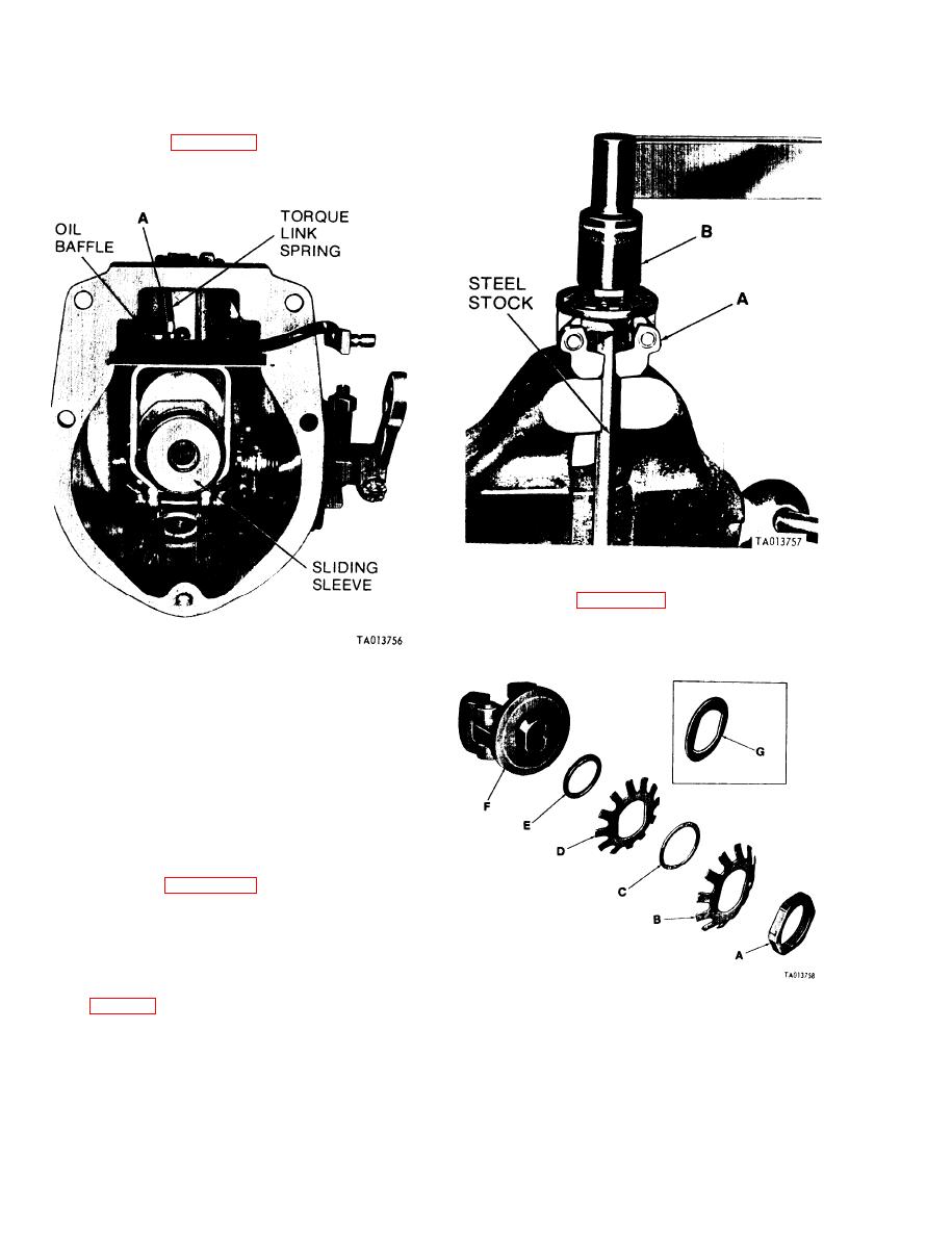
(21) Refer to figure 3-89 and install torque link
spring (A) from torque link pin to oil baffle.
Figure 3-90. Removing or installing spring disk adjusting nut.
(3) Refer to figure 3-91. Remove outer spring
disk (B) spring disk spacer (C) inner spring disk (D)
and spring disk spacer (E) and retainer if used, from
friction drive spider.
Figure 3-89. Installing oil baffle, sliding sleeve and torque link
spring (code A pumps).
3-26. Repair of Governor Weight and Spider
A s s e m b l y . a. Disassembly. Disassemble the
governor friction drive as follows:
(1) Before any disassembly of the friction drive
assembly, check clearance between the governor
weight pin and weight pin bushing using a dial
indicator. Maximum allowable clearance is 0.003 -
inch with weights in their outermost position. If
clearance is greater than 0.003-inch, replace the
complete governor weight and spider assembly.
(2) Refer to figure 3-90. Place friction drive
spider (A) on a piece of 3/8 x steel stock held in
vise. Remove spring disk adjusting nut using socket
wrench (B).
NOTE
Early model friction drive spider assemblies
were assembled with a retainer. If retainer
(G, fig. 3-91) is removed at disassembly it
Figure 3-91. Disassembling or assembling friction drive spider
must be reinstalled at assembly. Later model
and associated parts.
friction drive spider assemblies did not
utilize this part and reference to it can be
b. Inspection of Governor Weight and Spider
Assembly.
disregarded. Early code G pumps have a
special nut which requires use of spanner
(1) Inspect the fingers on the spring disks (B
wrench 5120-793-5046 for removal.
3-58
|
|
Privacy Statement - Press Release - Copyright Information. - Contact Us |
