 |
|||
|
|
|||
|
Page Title:
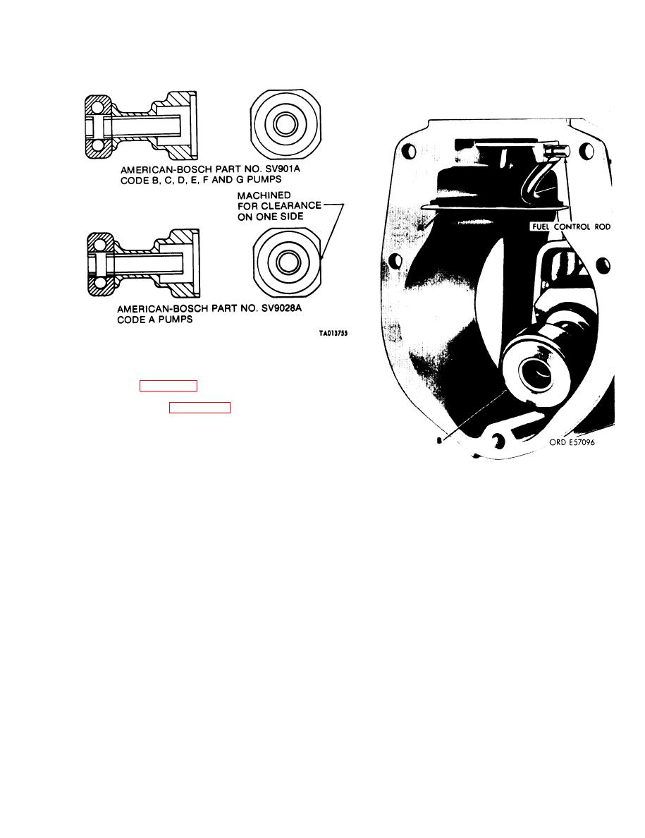
Figure 3-87. Identification of governor sliding sleeve assemblies. |
|
||
| ||||||||||
|
|
 TM 9-2910-226-34
Figure 3-87. Identification of governor sliding sleeve assemblies.
NOTE
Refer to figure 3-86 and 3-87 for selection of
sliding sleeve and oil baffles.
(20) Refer to figure 3-88. Install oil baffle (A)
and sliding sleeve (B) on pins in fulcrum lever.
NOTE
The governor springs, spacers, and end cap
will be installed after governor is installed on
fuel injection pump housing.
Figure 3-88. Installing oil baffle and sliding sleeve.
3-57
|
|
Privacy Statement - Press Release - Copyright Information. - Contact Us |
