 |
|||
|
|
|||
|
Page Title:
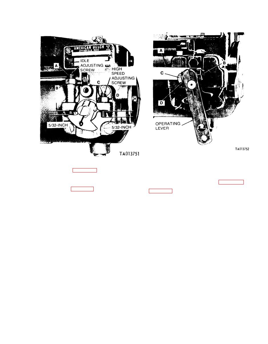
Figure 3-83. Installing high speed and idle adjustment screws. |
|
||
| ||||||||||
|
|
 TM 9-2910-226-34
Figure 3-84. Checking operating lever clearance using a feeler gage
Figure 3-83. Installing high speed and idle adjustment screws.
NOTE
(17) Refer to figure 3-59 and install dust cover
Sub-paragraph (19) below applies to code A
(D), lockwasher (C) and machine bolt (B). Torque
pumps only.
tighten dust cover bolt to 50-60 inch-pounds. Do not
(19) Refer to (16) above and figure 3-83 and
install lead seal safety wire at this time.
install idle and high speed adjusting screws. Refer to
(18) Refer to figure 3-84. Insert a feeler gage (A)
to obtain a clearance of 0.002 to 0.004 inch between
piece on this pump. Install screw (A), lockwasher (B)
the operating lever and dust cover. Loosen clamping
and nut (C). Install operating lever assembly in up
screw (B), lockwasher (C), and nut (D). Move lever
position on operating shaft (D) with the split in lever
as necessary to obtain this clearance. Torque tighten
alined with scribe mark on end of operating shaft
nut to 70-75 inch-pounds.
|
|
Privacy Statement - Press Release - Copyright Information. - Contact Us |
