 |
|||
|
|
|||
|
|
|||
| ||||||||||
|
|
 TM 9-2835-255-34
GAS TURBINE POWER UNIT REPLACEMENT (Sheet 14 of 30)
NOTE
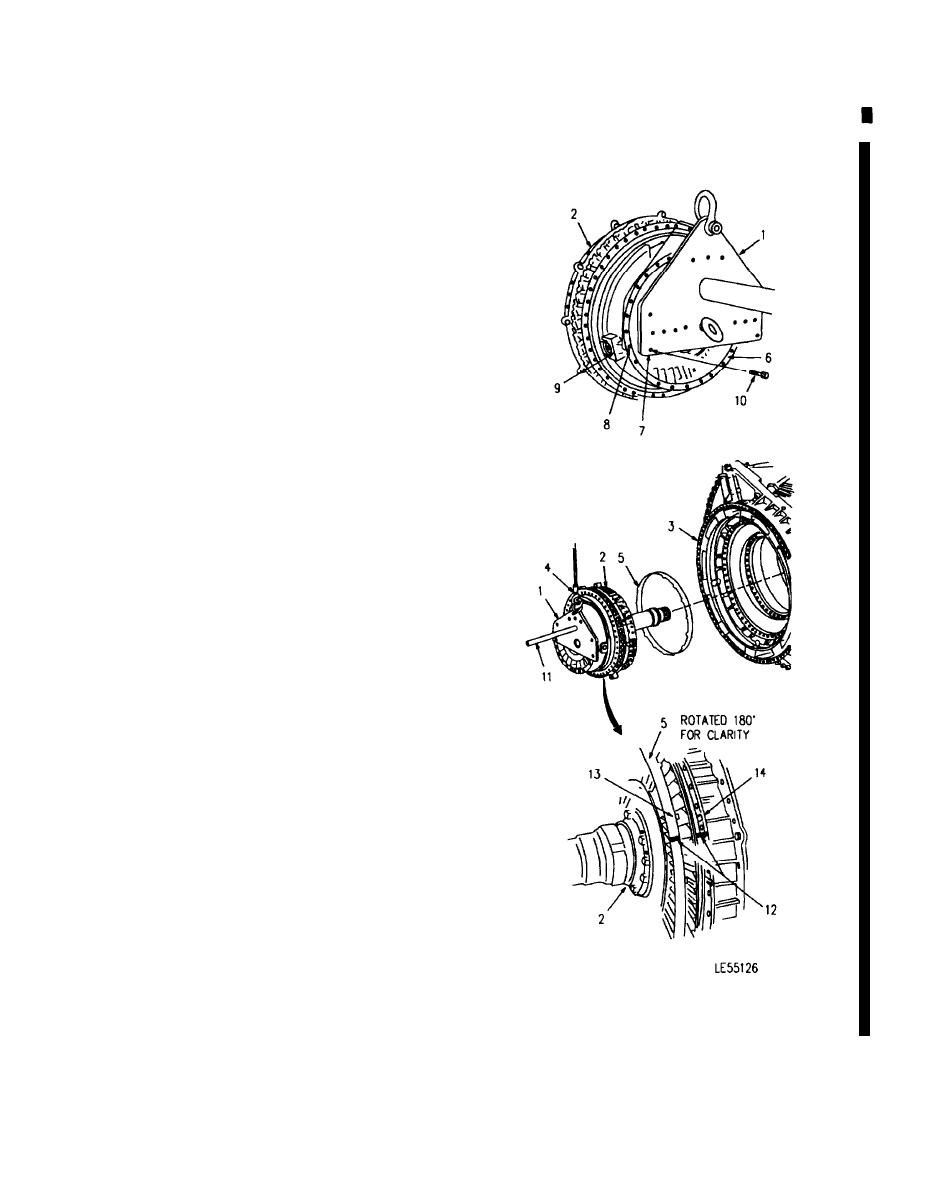
Proper orientation of lifting sling (1) on gas
turbine power unit (2) will ensure align-
ment with regenerator assembly (3) during
reassembly.
2. INSTALL LIFTING SLING (1) CHAIN HOIST
HOOK (4) AND MECHANICAL GUARD (5) ON GAS
TURBINE POWER UNIT (2).
a.
Position lifting sling (1) against mechanical
housing flange (6) so that bottom left bolt hole
(7) aligns with bolt hole (8) adjacent to oil feed
mounting boss (9). Secure using seven bolts
(10) provided with lifting sling (1).
b. Attach chain hoist hook (4) to lifting sling (1).
Use lifting sling handle (11) to support gas
turbine power unit (2) while lifting the assem-
bly.
NOTE
Mechanical guard (5) and gas turbine
power unit (2) must be retained as a
matched set. During installation, make
sure mechanical guard (5) is positioned
on gas turbine power unit (2) with match
marks (12), tabs (13) and grooves (14)
aligned.
c.
Gently raise gas turbine power unit (2) from
work surface and install mechanical guard (5)
using match marks (12) made during disas-
sembly. Make sure tabs (13) are installed in
grooves (14).
Go on to Sheet 15
6-75
Change 6
|
|
Privacy Statement - Press Release - Copyright Information. - Contact Us |