 |
|||
|
|
|||
|
Page Title:
INSTALL PULLER AND REMOVE ADAPTER AND SHAFT ASSEMBLY |
|
||
| ||||||||||
|
|
 TM 9-2835-255-34
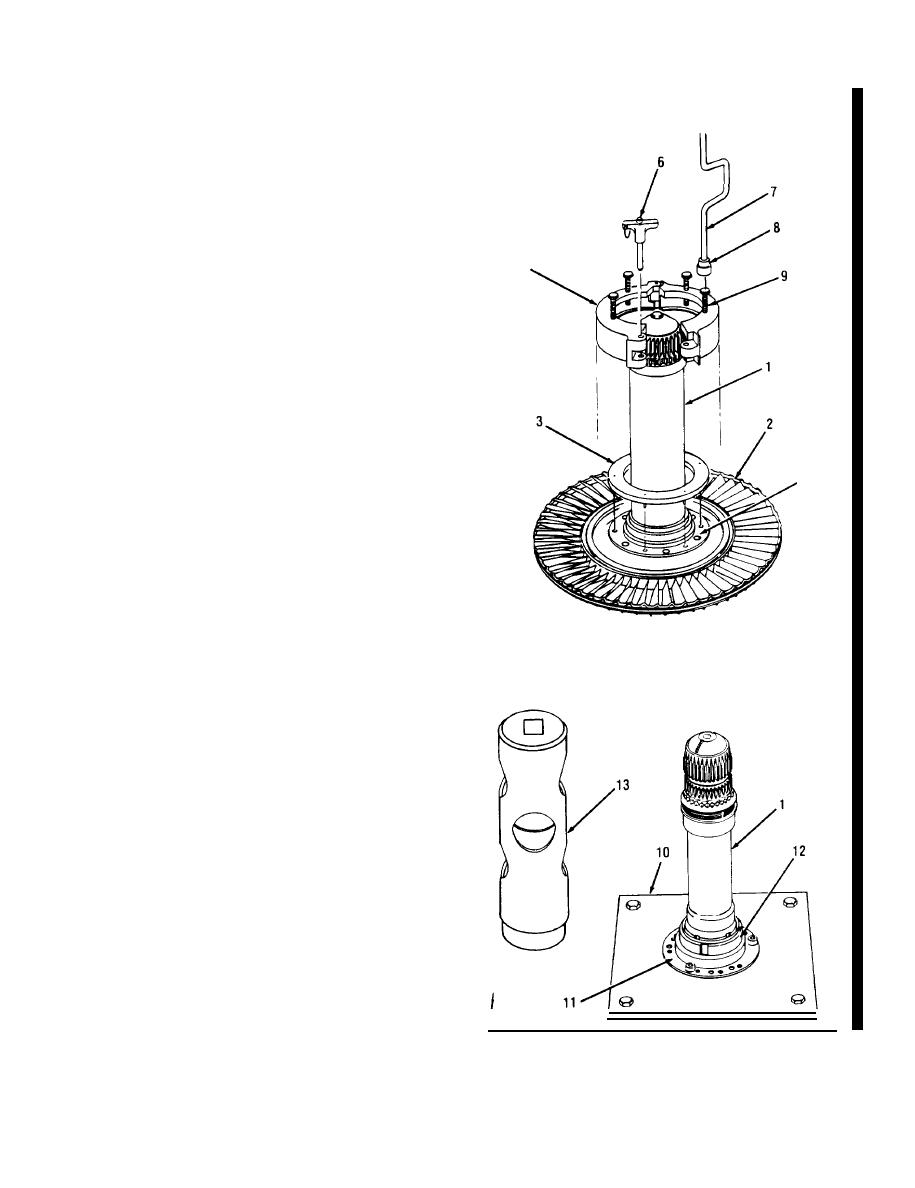
ADAPTER AND SHAFT ASSEMBLY REPAIR (Sheet 3 of 8)
INSTALL PULLER AND REMOVE
5
..
ADAPTER AND SHAFT ASSEMBLY (1)
FROM TURBINE ROTOR (2).
a.
ring (3) over adapter and shaft
Install
assembly (1). Aline pins of ring with small
holes in flange (4) of adapter and shalt
5
assembly (1).
b. install clamp (5) around flange (4). Make
sure edge of clamp (5) is under edge of
flange (4). Install locking pin (6).
c.
Using crank (7) and socket (8), tighten the
four jackscrews (9) in a staggered se-
quence, one quarter turn at a time, until
adapter and shaft assembly (1) is separated
from turbine rotor (2).
d. Remove puller from adapter and shaft
4
assembly (1).
INSTALL AND SECURE ADAPTER AND
6.
SHAFT ASSEMBLY (1) ON HOLDING
FIXTURE (10) WHICH IS SECURED ON
WORK SURFACE.
DISCONNECT SHAFT FROM SPLINED
7.
ADAPTER (11).
Straighten deformed portion of retaining
a.
nut (12) from shaft.
Place spanner wrench (13) over shaft and
b.
engage retaining nut (12). Turn clockwise
and loosen retaining nut (12) until shaft
separates from adapter (11).
t
1
I
Go on to Sheet 4
Change 4 6-39
|
|
Privacy Statement - Press Release - Copyright Information. - Contact Us |