 |
|||
|
|
|||
|
|
|||
| ||||||||||
|
|
 TM 9-2835-255-34
ADAPTER AND SHAFT ASSEMBLY REPAIR (Sheet 2 of 8)
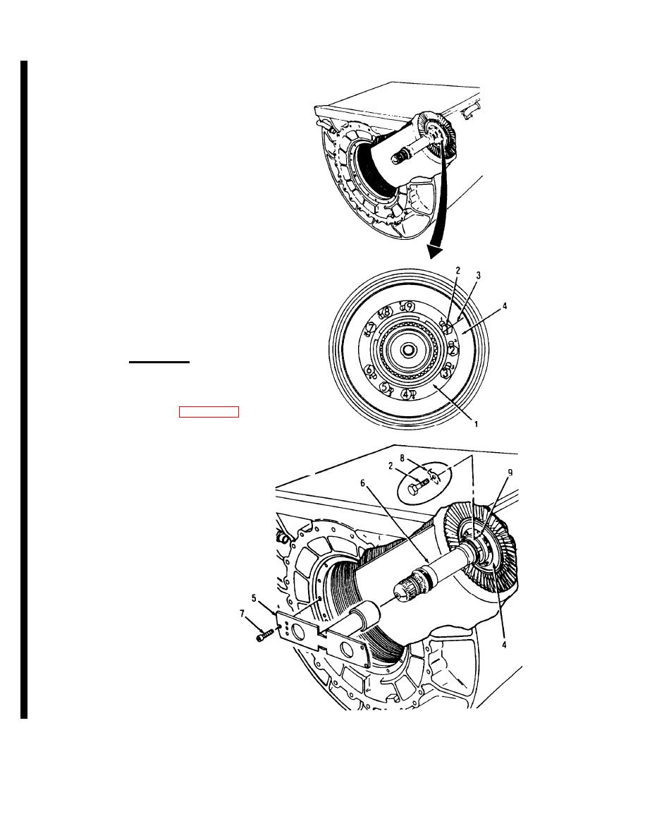
USING FLASHLIGHT, LOCATE NUM-
2.
BERED MATCHMARKS ON SPLINED
ADAPTER (1) AND NINE BOLTS (2). WITH
MARKER. PLACE A LINE (3) ACROSS
BOLT NUMBERED 1 (2), SPLINED
ADAPTER (1) AND TURBINE ROTOR (4).
3.
INSTALL HOLDING FIXTURE (5) OVER
END OF ADAPTER AND SHAFT
ASSEMBLY (6) AND ATTACH TO
RECUPERATOR WITH THREE BOLTS (7).
DISCONNECT ADAPTER AND SHAFT
4.
ASSEMBLY (6) FROM TURBINE ROTOR
(4).
a.
Bend tabs of nine keywashers (8).
b.
Remove bolts (2) and keywashers (8).
Discard keywashers (8). Remove holding
fixture (5).
CAUTION
Do not damage or discard bolts (2). The nine bolts
(2), and holes (9) in the splined adapter are num-
bered and matched. If bolts (2) are damaged. replace
rear engine subassembly (page 6-28).
c.
Gently rock adapter and shaft assembly (6)
off the turbine rotor (4). if adapter and
shaft assembly (6) cannot be removed. do
step 5. If removed, go to step 6.
Go on to Sheet 3
6-38 Change 4
|
|
Privacy Statement - Press Release - Copyright Information. - Contact Us |