 |
|||
|
|
|||
|
Page Title:
INTERMEDIATE (LOW PRESSURE) HOUSING (TOP HALF) REPLACEMENT (Sheet 1 of 6) |
|
||
| ||||||||||
|
|
 INTERMEDIATE (LOW PRESSURE) HOUSING (TOP HALF) REPLACEMENT
(sheet 1 of 6)
TOOLS: General mechanic's tool kit: automotive (SC 5l8O-9O-N26)
Inserted hammer face (Item 1, Appendix D)
Inserted hammer face holder (Item 2, Appendix D)
SUPPLIES: Antiseize compound (Item 2, Appendix B)
Cotter pin (Item 10, Appendix E)
Cotter pin (Item 11, Appendix E)
Gasket (Item 1, Appendix E) (2 required)
Keywasher (Item 6, Appendix E)
Lockwasher (Item 2, Appendix E) (14 required)
Lockwasher (Item 7, Appendix E)(2 required)
Self-locking nut (Item 9, Appendix E) (12 Required)
Self-locking nut (Item 3, Appendix E) (5 Required)
Self-locking nut (Item 8, Appendix E) (2 Required)
Shortening compound (Item 20, Appendix B)
Technical beeswax (Item 3, Appendix B)
EQUIPMENT CONDITION: Engine starter motor removed (TM 20-1)
Plenum-to-engine plain seal removed (TM 20-1)
Screen assembly (engine air inlet) removed (TM 20-1)
Pressure fluid filter double angle bracket removed (TM 20-1)
Tube assembly (top of inlet guide vane actuating cylinder) removed (TM 20-1)
Tube assembly (bottom of inlet guide vane actuating cylinder) removed (TM
20-1)
Tube assembly (No. 5 and 6 bearings) removed (TM 20-1)
Tube assembly (No. 2 and 3 bearings) removed (TM 20-1)
Tube assembly (forward reduction gearbox) removed (TM 20-1)
Inlet guide vane feedback control assembly removed (TM 20-1)
Tube assembly (No. 2 and 3 bearing feed) removed (TM 20-1)
Tube assembly (No. 1 bearing feed) removed (TM 20-1)
Ignition electrical lead removed (TM 20-1)
Bleed valve rod removed (TM 20-1)
REMOVAL:
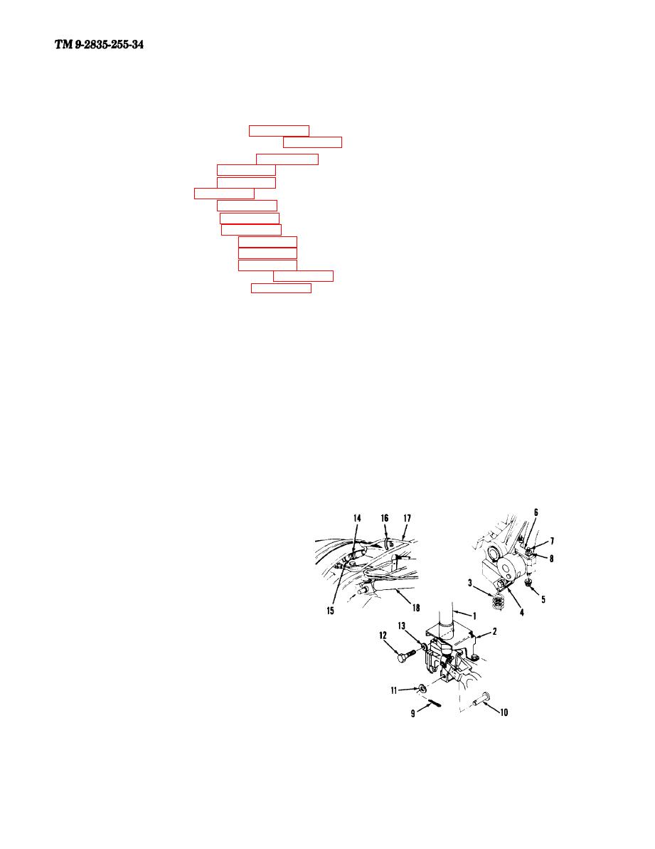
1. REMOVE ASSEMBLED ACTUATING
CYLINDER (l) AND BRACKET(2).
a. Unhook spring (3) from connecting link (4).
Remove two selflocking nuts (5). Lift off
assembled stop plate (6) with studs (7) and
nuts (8) attached.
b. Remove cotter pin (9), pin (10),
and washer (11). Remove two bolts (12) and
lockwashers (13).
c .Remove connector (14) from sensor (15).
Remove tiedown strap (16). Move cable lead
(17) away from link (18).
Go on to Sheet 2
5-6 Change 2
|
|
Privacy Statement - Press Release - Copyright Information. - Contact Us |